Although slit-based profilers were designed to measure continuous-wave (CW) lasers, they can also work for pulsed-mode lasers.
Allen M. Cary, Photon Inc.
Measuring pulsed-beam lasers has generally required the use of a CCD array profiler. This is a reasonable solution for low-power lasers in the UV and visible wavelength range, but these require external attenuation when used with CCD cameras. Once the lasers leave the UV-VIS range, array cameras become extremely expensive.
Although low-frequency pulsed lasers operating in the 1 to 1000 Hz range have no real alternative to the array profiler, it is possible to measure kilohertz-frequency lasers with a slit-based profiler. This will allow the inherent advantages of minimal beam attenuation and a broad range of available wavelength response. Photon’s NanoScan profiler incorporates the peak-connect algorithm and software-controlled variable scan speed on all scanheads to enable the measurement of these pulsed lasers. This makes it useful for measuring Q-switched lasers and lasers operating with pulse width modulation (PWM) power control. Lasers with pico- and femtosecond pulse durations are being used in many applications. Although they add some additional complication to the measurement techniques, a slit profiler can be well suited to measure them.
PWM lasers
Many lasers, especially CO2 lasers, use pulse width modulation to control laser power levels. This is not true pulsed operation, but rather a reduction of the duty cycle to lower the average power. The beam operates as if it were continuous wave, and many operators do not realize that the laser is pulsing. However, when attempting to measure a PWM laser with a scanning slit profiler, it must be treated as a pulsed laser source.
To use the pulsed mode of a slit-based profiler, the laser’s pulse frequency must be at least several kilohertz, and the combination of the frequency and beam size must provide a sufficient number of pulses across the beam to generate a meaningful profile. Fifteen pulses are a reasonable minimum.
PWM lasers usually operate around 10 kHz. The relationship of the beam size and frequency is a fairly simple mathematical model. With the NanoScan, for instance, drum speed is software controlled from 1.25 to 20 Hz. There are two available drum sizes; the standard head has a drum diameter of 42 mm, and the large-aperture and high-power heads use a drum with an 84 mm diameter.
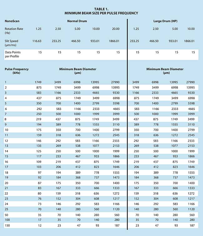
On the 42 mm drum at the 1.25 Hz rotation rate, the slits travel at around 116.6 mm/s or 116.6 µm/ms. At a 10 kHz laser repetition rate, a 175 µm beam would have 15 pulses during the time that the slit was traversing it. This would provide enough data to generate a meaningful profile. A smaller beam would require a faster pulse rate, a larger one could perhaps run at a lower repetition rate. For example, a 1.0 mm beam could be measured with a pulse rate as low as 2 kHz and still provide a profile.
It is recommended that the 1.25 Hz scan speed be used for pulsed beams. However, if the beam sizes are large enough or the pulse rates are fast enough, the measurement can be sped up by increasing the scan speed to 2.5 Hz or above. The NanoScan software will generate a warning if the scan rate is set too high for the pulse rate or beam size. This warning algorithm is based on having at least 15 pulses across the beam to provide a minimum of 2 percent accuracy.
Calculations
Table 1 lists calculated minimum beam diameters at a given pulse frequency for each of the drum sizes and for a desired number of pulses per profile. The more pulses per profile, the more accurate the measurement is likely to be. The formula is fairly simple. Because of the 45° angle of the slits to the direction of rotation, the actual speed of the slits is the drum speed divided by the square root of two.

Where:
- v = drum velocity in microns per millisecond
- f = pulse frequency in kilohertz
- N = pulses per profile
- Dmin = minimum beam diameter in microns
The pulsed beams can be measured at any rotation rate, but it is recommended that the scan rate be 1.25 or 2.5 Hz unless the laser repetition rate is above 50 kHz. The larger drum used in the large-aperture and high-power versions of the NanoScan causes the slits to move faster at any given rotation rate because of the larger circumference. For this reason, the minimum beam sizes are larger for the large drum. The peak-connect algorithm finds the highest peak pulse. Using the frequency value entered by the operator, it finds the other peaks and connects them to generate a smooth beam profile. It is important that the exact pulse frequency be entered into pulse acquisition parameters.
The earlier instruments only allowed the measurement of pulsed beams with the pyroelectric detector. NanoScan provides this capability with all scanheads and detectors. Beams with average powers that were too low to be measured with the pyroelectric detector can now be profiled using silicon or germanium scanheads. At very high laser repetition rates (e.g., >100 kHz) it may be better to operate the profiler in CW mode and let the filter smooth the beam. When this is preferable is dependent on the individual laser’s pulse performance. If inconsistent results are seen with a high-repetition-rate laser, it may be advisable to try the measurement both ways.
Q-switched lasers
Another type of pulsed laser, operating in the kilohertz pulse rate regime, is the Q-switched laser. These use the pulsing to increase, rather than decrease, their effective power. Because the laser power is concentrated into a short pulse, the peak power of each pulse increases while maintaining a low average power. In order to measure these lasers, the same mathematical relationship of pulse rate to beam diameter applies, but there is an additional complication; the peak power of the pulses may exceed the damage thresholds of the NanoScan even though the average power remains within the operating space.

CW beams are measured as power (P) in watts; pulsed beams as energy (E) in joules. Therefore it is necessary to understand the beam’s energy (Epulse) to determine whether the unattenuated beam can be directly measured with the NanoScan.
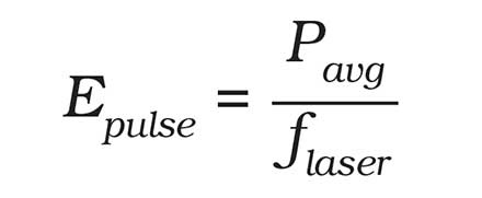
Therefore a beam with an average power of 300 W with a pulse frequency of 8 kHz will have energy as follows:

The power density per pulse is also a function of the pulse duration τ. This is also important in understanding the potential damage to the profiler. Taking the above example, if the pulse duration is 1 ms, then:

Pico- and femtosecond lasers
When the pulse duration of the laser becomes very short, such as with pico- and femtosecond lasers, the peak power of the pulses can become very large. This creates some added complications when determining the type of scanhead that can safely measure these beams. In addition to the average power of the beam, which is used to determine the proper operating space of a given scanhead, it is important to know the energy density of the pulses. The energy density must be below the damage threshold for the aperture material, and the average power must fall within the operating space of the scanhead for it to be possible to measure the beam without additional attenuation. To determine the energy density, first use the above formula for Epulse:
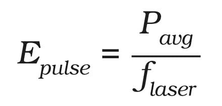
Most pico- and femtosecond lasers have both a high repetition rate and a fairly low average power. They use the short pulse duration to amplify the effective power of the laser beam. A typical laser that one might encounter would have an average power of 1.0 W and a repetition rate of 80 kHz. For this laser the Epulse would be:

Using this value, calculate the energy density for a given beam diameter by the following formula. Note that the energy density is presented as joules per square centimeter; therefore the beam area needs to be converted to centimeters in the formula. Unless the beam is wildly different from round, it is easiest to consider that the area will be that of a circle:
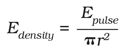
For a 100 µm beam at 12.5 µJ:
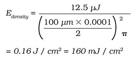
Once the energy density is calculated, it can be compared with the damage threshold for the aperture type and the wavelength range for the aperture material. The standard blackened slit material can only handle 10 mJ/cm2 before the blackening starts to ablate. For this reason, scanheads intended for use with these pico- and femtosecond lasers should have the reflective slits, regardless of the detector type or the average power of the lasers.
The wavelength of the laser also influences the energy density that the aperture material can withstand. For standard nickel alloy slits, the maximum energy density is 600 mJ/cm2 for the range of 190 to 400 nm; for 400 nm and above, the value is 1.0 J/cm2. For high-power copper slits, the values are 2.5 J/cm2 from 700 nm to 3 µm and 5 J/cm2 above 3 µm. Copper slits are not recommended for use below 700 nm. However, in some experiments we have seen better performance in the UV (at 355 nm) from copper slits. This may be attributed to the better heat dissipation of the copper material or the fact that the copper aperture material is thicker than the nickel alloy.
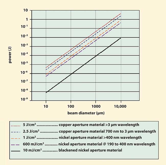
Figure 1. Damage threshold curves showing a comparison of energy per pulse at a given beam diameter with the appropriate threshold line for the aperture material and wavelength of use.
Figure 1 can be used in lieu of the calculation to compare the energy per pulse at a given beam diameter with the appropriate threshold line for the aperture material and wavelength of use. For the above case, 12.5 µJ energy at 100 µm would be below the 600 mJ damage line, but would certainly be well above the damage level for blackened apertures.
These estimates of damage threshold are primarily based on the relative reflectivity of the slit material. There are many other factors that may influence interaction of the laser beam and the aperture. At some level of power and pulse duration, this interaction may become nonlinear. In addition, surface finish, roughness, contamination, tarnish or oxidation can also affect the reflectivity of the materials. For this reason, these damage threshold values can only serve as a guideline, not an absolute guarantee. Use caution when measuring any new or unfamiliar laser system.