Optical systems design and analysis software is a key element in an optical engineer’s toolkit. Simulation allows virtual tinkering with a system problem before ever creating — and in some cases eliminating — a prototype. The results can be analyzed to determine real system performance and to suggest changes to optimize the design and enhance performance.
Breault Research Organization, Inc.
Illumination design has developed rapidly to include not only automotive headlamps and street lamps, but also backlit displays, fluorescent panel lighting, light-emitting diode or laser sources, and many other concepts that broaden the definition of the field. The combination of sophisticated software development tools, powerful desktop computers, and increasing optical design complexities continues to drive software applications for optical systems design and analysis. Only a few years ago, a typical user needed to be expert in systems administration and using scientific engineering software. Many users moved from writing their own analysis code to using others’ code, while still retaining a deep understanding of the underlying numerical methods and physical models.
Now, the changing dynamics of the typical user and technology industries in general have caused software authors to retool their objectives. Many users are assigned to find the solution to a problem outside their own discipline. Indeed, it is common for a mechanical or electrical engineer to be asked to solve a complex problem that involves optics. Increasingly, software must provide these designers the tools to leverage their existing knowledge without requiring that they become optical experts. However, it is still important to allow experts to push the technology envelope by providing comprehensive control of the tools.
There are two basic classifications for optical design and analysis software. The first includes classic lens design programs. These programs are used primarily where rays travel through the system in a sequential fashion. The optical systems are typically composed of lenses, mirrors and prisms. Examples include CODE V, OSLO and ZEMAX.
The second type includes nonsequential, general-purpose ray tracing programs in which the ray tracing function is more complex. These seek simulation results that better fit complete, real systems behavior. Stray light and scattering effects are real-world problems, and only the most sophisticated of the optical simulation tools have the capability to model these effects. These tools allow better simulation of real devices by including effects due to light hitting, the mechanical mounts, the housings or the ground edges of optics. Some of the nonsequential ray tracers also have a sequential mode that may be used under appropriate conditions to enhance performance. Examples of nonsequential ray tracing software would include ASAP, LightTools, FRED and TracePro.
The major players in the optical software arena are used predominately under Microsoft Windows, with the common graphical interface features promoting increased usability for today’s typical user. Authors are paying close attention to user interface design and are examining new techniques to educate and train users.
In computer programming, information flow may be considered in three basic steps: input, process and output. This flow concept is used internally in software within functions or routines. However, it also can be applied at a higher level by inputting or importing data into a system, processing and manipulating data within the system, and displaying the results from within the application and exporting the data out for further processing or display. The basic flow of work using these tools involves the creation of a description of the optical system geometry, the inclusion of sources, the tracing and analysis of rays through the system, and output of the analytical results.
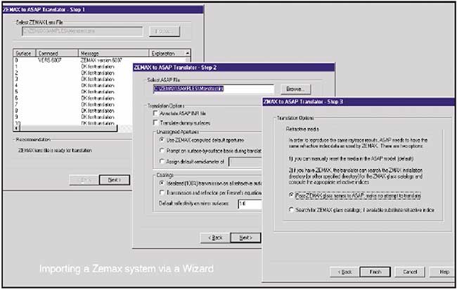
Figure 1. ZEMAX translator dialog.
The optical system
The optical system represented by software is composed of more than just lenses and mirrors. It can include baffles, mounting hardware or other components that may have an effect on the system. The system geometry may originate from within a computer-aided design (CAD) package, a lens design package, or in the native environment of the optical analysis tool. Techniques for bringing in system geometry from external design packages should be as integrated as is practical. A user expects to simply open a file with the common file-open dialog for importing data.
A program such as ASAP uses the Microsoft “Wizard” procedure, which walks the user through the process of importing a file. The ZEMAX, CODE V and OSLO lens design translators scan the file for potential problems and warn the user if any are encountered. A typical lens design translator dialog is shown in Figure 1.
The result is a ready-to-use input file in the native ASAP language.
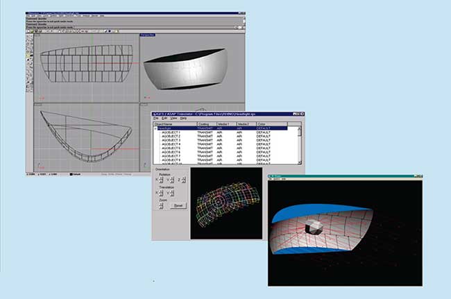
Figure 2. Translation of a CAD-based system into ASAP.
Importing system geometry from an external CAD system requires a CAD translator. With ASAP, the IGES import function remembers the optical properties assigned by the user during the translation. This simplifies reimporting during design iterations. The association of optical properties to objects is achieved through the standard IGES object-naming capability. The naming can be used in a hierarchical fashion for grouping related objects. This process is illustrated in Figure 2 as it flows from the CAD program, through the IGES translator, to the 3D Viewer in ASAP.
All optical design and analysis software available today has the ability to create system geometry from within the application. This technique is employed for system geometries with few nonoptical components of concern, less complex system geometries containing mechanical components, or when a CAD system is not available. In the lens design market, a common approach for entering lens elements is via a spreadsheet. This approach has also been adopted in nonsequential codes to provide a more convenient entry for new or infrequent users, as shown in Figure 3.
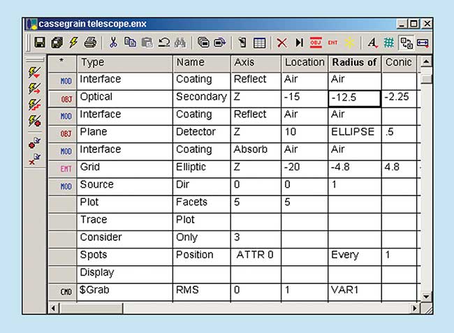
Figure 3. Spreadsheet-based optical model builder.
Creating sources
Ray tracing requires a light source, and all optical design programs provide that capability. It is important to be able to model the light source accurately for the best results in simulating an optical system. Source libraries and wizards, such as the one depicted in Figure 4, offer accurate source modeling. In this scheme, a bulb’s complete geometry may be entered (typically via a CAD system). All aspects of the bulb’s filament, filament strands and envelope are meticulously entered. In the case of nonfilament sources such as LEDs or arc lamps, the emitting geometry may be incomplete, but the ray sets provided by the libraries allow accurate description of their output. This approach is also used by Radiant Imaging’s Radiant Source, providing actual bulb characterizations derived from images captured by a CCD camera. These data can be imported into the design and analysis program.
The use of multiple sources may also be required, and in some cases color characteristics may be critical. To enable color analyses of an optical system, multiple sources, or sources with particular spectral distributions, may be created.
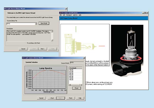
Figure 4. Light source libraries allow users to drop common
sources into their model with ease.
Ray tracing and analysis
Once a system has been created and a light source selected, ray tracing can begin.
In decades past, optical engineers might have run computer simulations with 1000 or 10,000 rays — a limit imposed by computer speed and storage. Other factors that determine ray trace speeds include sequential vs. nonsequential ray tracing. Sequential ray tracing traditionally is faster, though nonsequential software may also include a sequential mode for enhanced performance. Efficient ray tracing is crucial because tracing millions, even tens of millions, of rays is required for accurate analysis. Thanks to the proliferation of inexpensive computing, this may still be accomplished as quickly as the "hand-tracing" of a handful of rays a couple of decades ago. A simple example of an automotive head-lamp showing a few traced rays is shown in Figure 5.
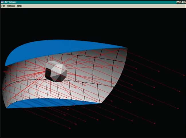
Figure 5. Ray trace of an automotive headlamp design.
The ray trace, the particular paths the rays take as they travel through the system, may be analyzed to characterize system performance. The information sought may include irradiance plots in particular planes, radiant intensity plots as a function of angle for a lamp, a systematic search for zones in the system where a specific energy density is exceeded, or the color-matching characteristics of the light on a detector, as a few examples. These may be single numbers, matrices of data corresponding to a map of values across an area or volume of space, or graphical representations to allow visualization.
Programs must produce quality graphics both internally, for the designer’s interactive evaluation, and to export for further processing, visualization and presentation, as in the examples of Figure 6. Applications may rely on the cut-and-paste technique for reports or presentations, while others may save to files such as Windows metafile format (WMF), a vector file format that enables them to rescale the image for a report or presentation without distortion.
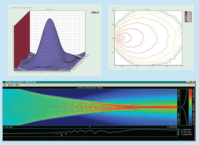
Figure 6. Examples of graphical output of analyses.
The ability to export analysis data for further processing is a plus. Examples include simple formats such as text output that can be read easily into packages such as Microsoft Excel, or more complex packages such as Interactive Data Language (IDL) by Research Systems or Mathematica by Wolfram Research.
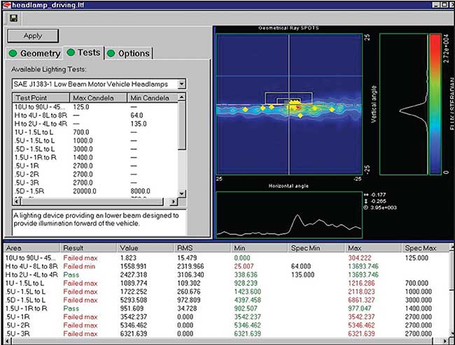
Figure 7. An automotive exterior lighting test module provides specialized information on standards compliance.
Modular capability, along with providing a migration path to take you from your current to future needs, is important if you are on a limited budget or just getting started. Some software packages are composed of modules that allow à la carte purchases. Modules may include various import/export capabilities such as CAD or lens design programs, as well as additional features of the software itself such as coherent or polarization capabilities. One relevant example of a special-purpose add-on module is shown in Figure 7. This module provides the ability to test automotive exterior lighting designs against standard test points of SAE, ECE or MVSS standards, as well as user-entered test points for custom or new applications.
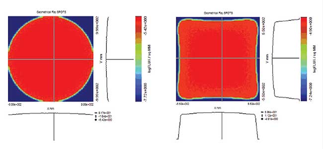
Figure 8. Input, circular energy distribution and output, square energy distribution on screen after reflector optimization.
A key need for all forms of optical analysis programs is an ability to optimize the performance of the optical system. Optimization consists of three separate components: a list of design goals or targets, a set of variables and an appropriate optimization algorithm. The optimization algorithm is used to systematically adjust any defined variables so that the system performance best matches the design goals.
In ASAP, several optimization algorithms are available for both imaging as well as nonimaging design. A wide range of ray interrogation tools are available to define any necessary optimization target. Optimization can be performed on any surface, including Bezier-based surfaces, Figure 8 demonstrates using ASAP to optimize the shape of reflector required to transform an input circular energy distribution into a uniform square illumination pattern on a screen with a required size and location.
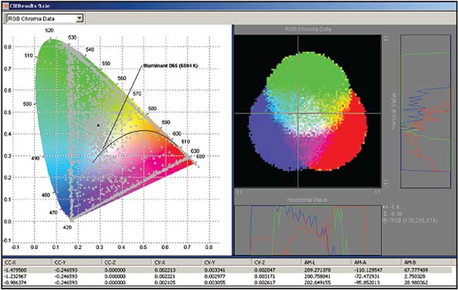
Figure 9. CIE analysis of source mixing.
The role of color in illumination has become increasingly important in recent years. A number of standard analysis techniques may be used to quantify the color in a system, such as matching to a reference white standard, compliance with traffic signal color requirements, or basic visual appearance. An example of a colorimetric analysis using CIE colorimetry standards is shown in Figure 9.
Optical analysis software continues to evolve from a design accessory towards full integration with manufacturing processes. This adaptation drives engineering of tools to solve interdisciplinary problems, and to use common design workflows across various disciplines. Finally, it allows engineers with varied backgrounds to work on a shared problem, and it promotes highly collaborative workflows. This promotes thorough, practical, manufacturable designs, and makes the entire product life cycle more manageable and efficient.