Nothing has changed the world of communications as much as the development and implementation of optical fiber. This article provides the basic principles needed to work with this technology.
Engineering and Marketing Staff, OFS
Optical fibers are made from either glass or plastic. Most are roughly the diameter of a human hair, and they may be many miles long. Light is transmitted along the center of the fiber from one end to the other, and a signal may be imposed. Fiber optic transmission systems are superior to metallic conductor-based in many applications. One of the greatest advantages is its bandwidth. Because of the wavelength of light, it is possible to transmit a signal that contains considerably more information than is possible with a metallic conductor — even a coaxial conductor. Other advantages include:
• Electrical Isolation — Fiber optics do not need a grounding connection. Both the transmitter and the receiver are isolated from each other and are therefore free of ground loop problems. Also, there is no danger of sparks or electrical shock.
• Freedom from EMI — Fiber optics are immune to electromagnetic interference (EMI), and they emit no radiation themselves to cause other interference.
• Low Power Loss — This permits longer cable runs and fewer repeater amplifiers.
• Lighter and Smaller — Fiber weighs less and needs less space than metallic conductors with equivalent signal-carrying capacity.
Copper wire is about 13 times heavier. Fiber also is easier to install and requires less duct space.
Applications
Some of the major application areas of optical fibers are:
• Communications — Voice, data, and video transmission are the most common uses of fiber optics, and these include:
– Telecommunications
– Local area networks (LANs)
– Industrial control systems
– Avionic systems
– Military command, control, and communications systems
• Sensing — Fiber optics can be used to deliver light from a remote source to a detector to obtain pressure, temperature, or spectral information. The fiber itself can also be used as a distributed sensor to measure a number of environmental effects, such as temperature, strain, and acoustic signal. Environmental changes along the length of the fiber affect the fiber properties in ways that can be detected.
• Power Delivery — Optical fibers can deliver remarkably high levels of power for tasks such as laser cutting, welding, marking, and drilling. Optical fiber can also be used to deliver power remotely for devices in places where electricity is not available.
• Illumination — A bundle of fibers gathered together with a light source at one end can illuminate areas that are difficult to reach — for example, inside the human body, in conjunction with an endoscope. Also, they can be used as a display sign or simply as decorative illumination.
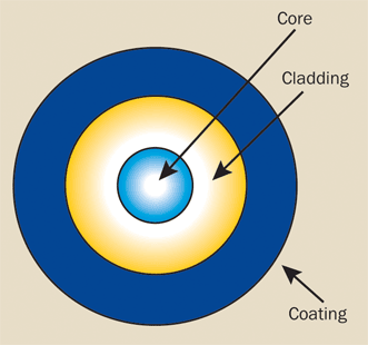
Figure 1. An optical fiber consists of a core, cladding, and coating.
Construction
An optical fiber consists of three basic concentric elements: the core, the cladding, and the outer coating (Figure 1).
The core is usually made of glass or plastic, although other materials are sometimes used, depending on the transmission spectrum desired.
The core and cladding form a waveguide that is essential to the light transmitting portion of the fiber. The cladding usually is made of the same material as the core, but with a slightly lower index of refraction (usually about 1% lower). This index difference causes total internal reflection to occur at the index boundary along the length portion of the fiber so that the light is transmitted down the fiber and does not escape through the sidewalls.
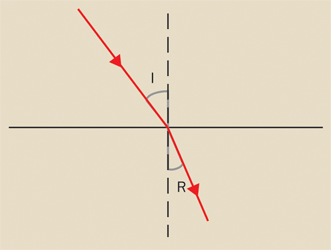
Figure 2. A beam of light passing from one material to another of a different index of refraction is bent or refracted at the interface.
The coating usually comprises one or more coats of a polymer material to
protect the fiber from the physical environment. Sometimes additional polymer layers and metallic
sheaths are added to the coating for further physical protection.
Optical fibers usually are specified by their size, given as the outer diameter of the core, cladding, and coating. For example, a 62.5/125/250 would refer to a fiber with a 62.5-µm diameter core, a 125-µm diameter cladding, and a 0.25-mm outer coating diameter.
Principles
The refractive index, denoted as n, is a key property of optical materials. It represents the ratio of the velocity of light in vacuum to its velocity in the material itself. If light transitions between materials with differing refractive indices, it will bend or refract at the boundary (Figure 2).
Refraction is described by Snell’s law:
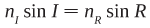
where nI and nR are the indices of refraction of the materials through which the beam is refracted and I and R are the angles of incidence and refraction of the beam. If the angle of incidence is greater than the critical angle for the interface, the light is reflected back into the incident medium without loss by a process known as total internal reflection (Figure 3).
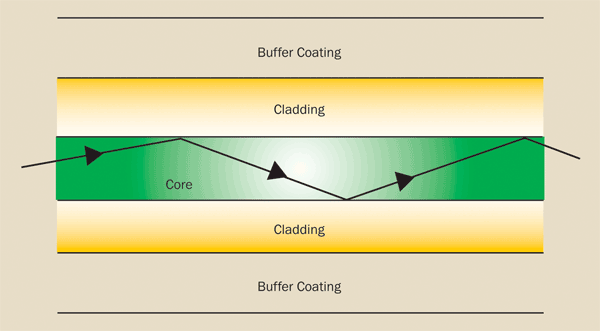
Figure 3. Total internal reflection allows light to remain inside the core of the fiber.
Watch a video definition of total internal reflection.
Modes
As light traverses through a fiber — similar to how microwaves are guided through a waveguide — each reflective boundary induces a phase shift. Within the optical fiber, a limited and discrete set of pathways exists (referred to as modes) that yield constructive phase shifts which amplify and support transmission. Each mode propagates at a distinct angle relative to the axis of the fiber, resulting in varying path lengths from entry to exit within the fiber. The unique mode that follows the fiber's length without sidewall reflections is what constitutes a single-mode fiber. The precise count of modes that an optical fiber can support depends on factors like light wavelength, as well as the diameter and refractive index of the fiber's core.
Attenuation
Signals lose strength as they are propagated through the fiber; this is known as attenuation. Attenuation is measured in decibels (dB) with the relation:
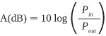
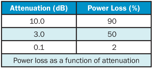
where Pin and Pout refer to the optical power going into and coming out of the fiber. The table below shows the power typically lost in a fiber for several values of attenuation in decibels.
Fiber attenuation is expressed in dB/km at a specific wavelength since it is wavelength dependent. To fully describe the dependence, an attenuation spectrum is commonly used. Typical values range from 10 dB/km for step-index fibers at 850 nm to a few tenths of a dB/km for single-mode fibers at 1550 nm.
Optical fiber attenuation can occur due to several factors:
• Rayleigh Scattering — This occurs when microscopic-scale variations in the fiber's core refractive index result in light scattering, which leads to significant optical power loss. It is more pronounced at shorter wavelengths and tends to be less impactful at longer wavelengths. In modern optical fibers, this scattering is the dominant cause of loss, typically representing up to 90% of total attenuation.
• Absorption — Absorption can be caused by impurities such as OH groups in the core. Advances in manufacturing technology have minimized the levels of impurities. As a result, within the fiber's transmission window, the impact of absorption on signal loss is minimal.
• Bending — Micro-scale level imperfections, micro-bend, created during manufacturing might impose small distortion from an ideal waveguide structure in the fiber, leading to light escaping from the core if it strikes the core/cladding boundary with insufficient angle. Furthermore, physically bending, macro-band, the fiber too tightly — beyond its specified bend radius — can also lead to losses. This sensitivity to bending is quantified by measuring dB/km loss for given bend radii and wavelengths.
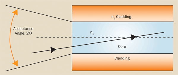
Figure 4. Numerical aperture depends on the angle at which rays enter the fiber and on the diameter of the fiber’s core.
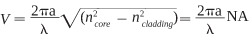
Numerical aperture
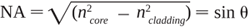
Numerical aperture (NA), shown in Figure 4, is the measure of maximum acceptance angle at which light rays will enter and be conducted down the fiber. This is represented by the following equation:
Dispersion
As the optical pulses travel the length of the fiber, they are broadened or lengthened in time. This is called pulse broadening and is caused by dispersion. Because the pulses eventually will become so broadened that they begin to overlap each other and corrupt the data, dispersion sets an upper limit on the data-carrying capabilities of a fiber. There are three principal causes for this broadening:
• Chromatic Dispersion — Light with different wavelengths travel at different velocities down the fiber. Because typical light sources provide power over a series or range of wavelengths, rather than from a single discrete spectral line, the pulses must spread out along the length of the fiber as they proceed. The high-speed lasers used in communications have very narrow spectral output specifications, greatly reducing the effect of chromatic dispersion.
• Modal Dispersion — This occurs when various fiber modes travel at distinct angles, creating slightly different path lengths. Consequently, the higher-order modes arrive later at the fiber's output than the lower-order modes.
• Waveguide Dispersion — Stemming from the fiber's physical shape, this less common type of dispersion causes varying propagation speeds for the different modes.
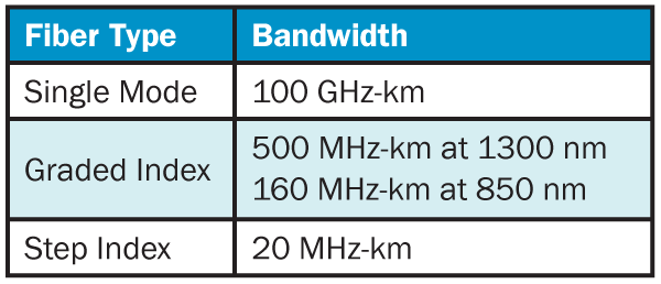
Bandwidth
Bandwidth defines the capacity of an optical fiber to transmit data, quantified by the product of signal frequency and transmission distance (common units include MHz-km or GHz-km). This is because fiber bandwidth is inversely related to its length. As an illustration, a fiber rated at 400-MHz-km can carry a frequency of 400 MHz up to 1 km, or alternatively, carry a lower frequency of 20 MHz over a longer span of 20 km. The major constraint on bandwidth is pulse spreading which is caused by modal and chromatic variations within the fiber. Standard bandwidth values for various fiber types are as follows:
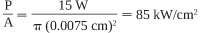
Power transmission
The transmission capacity of a fiber, or the maximum power it can handle without damage, is typically measured by the highest allowable power density. This power density is calculated as the laser's maximum power output divided by the beam's cross-sectional area. For example, a 15-W laser beam focused onto a 150-µm diameter spot produces a power density of
The output of a pulsed laser (typically specified in millijoules of energy per pulse) must first be converted to power per pulse. For example, a pulsed laser that produces 50 mJ in a 10-ns pulse provides an output power of
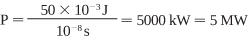
The power density then can be calculated from the spot size.
For optimal energy transmission along a fiber, it is essential that the fiber end surfaces are perfectly smooth, polished, and perpendicular to both the fiber axis and the incoming beam of light. Additionally, the light beam's diameter should be around half that of the core's area (or its diameter) to prevent energy loss to the cladding, as this can rapidly damage polymer-clad silica fibers. Therefore, for applications with high power density, utilizing silica-clad silica fibers is advisable.
Fiber types
There are primarily three categories of optical fiber: single mode, multimode graded index, and multimode step index. These types differ in the manner in which light is transmitted through the fiber, and this variation is influenced by the light's wavelength as well as the physical structure of the fiber. Examples of how they propagate light are shown in Figure 5.
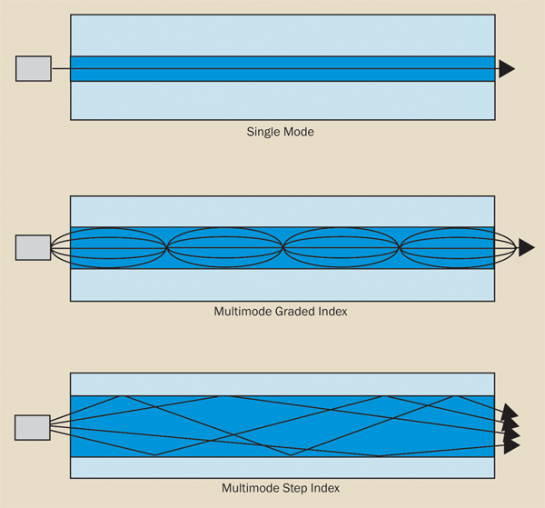
Figure 5. Modes of fiber transmission.
Single mode
Only the fundamental zero-order mode is transmitted in a single-mode fiber. The defining feature of single-mode fiber is its cutoff wavelength, which relies on the core size, numerical aperture (NA), and operational wavelength. If operating below this cutoff wavelength, additional higher-order modes can propagate and alter the properties of the fiber.
Single-mode fiber carries just the fundamental mode, removing modal dispersion, which is the main reason for pulse overlap. Therefore, single-mode fibers offer a significantly greater bandwidth compared to multimode fibers, allowing pulses to be sent in closer succession without overlapping. Owing to this increased bandwidth, single-mode fibers are employed in contemporary long-distance communication systems. The core diameters usually range from 5 to 10 micrometers.
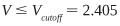
The actual number of modes that can be propagated through a fiber depends on the core diameter, the numerical aperture, and the wavelength of the light being transmitted. These may be combined into the normalized frequency parameter or V number,
where a is the core radius, λ is the wavelength, and n is the index of the core and the cladding. The condition for single-mode operation is that:
Perhaps more important and useful is the cutoff wavelength. This is the wavelength below which the fiber will allow propagation of multiple modes and can be expressed as:

A fiber is typically chosen with a cutoff wavelength slightly below the desired operating wavelength. For lasers typically used as sources (with output wavelengths between 850 and 1550 nm), the core diameter of a single-mode fiber is in the range of 3 to 10 µm.
Multimode graded index
Multimode fibers have much larger core diameters than single-mode fibers, allowing for a higher number of propagated modes and easier connectorization.
Multimode fibers with a graded-index profile feature a core whose refractive index decreases from the center outward, enabling higher order mode light to travel faster. This creates nearly equal travel times for different modes and reduces greatly modal dispersion.
Consequently, graded-index fibers offer significantly higher bandwidths than step-index fibers but are still outperformed by single-mode fibers. Their typical core sizes are 50, 62.5, and 100 µm, and they are primarily used in mid-range communication like local area networks.
Multimode step index
In a step-index multimode fiber, the core's refractive index remains constant throughout until it abruptly shifts to that of the cladding at the core-cladding interface, resembling a step. This characteristic causes the various modes in the fiber to traverse differing lengths, resulting in more model dispersion that in turn limits the transmission distance.
These fibers come in core sizes ranging from 100 to 1500 micrometers and are particularly apt for high-power-density applications, including the delivery of laser power in medical and industrial settings.