James R. Joubert and Deepak K Sharma, Photometrics
CCD sensors have been the staple for scientific imaging for decades.1 The addition of electron
multiplication to CCDs also has extended their utility to applications where higher
sensitivity is needed because of extremely low light conditions.2 CMOS sensors,
which in the past have displayed limited performance, seem to have improved in quality
recently, to the point of potentially competing with CCDs and electron-multiplying
CCDs (EMCCDs) in the scientific imaging arena.
Here we investigate scientific-grade CMOS and EMCCD performance
under low-light microscopy conditions by comparing signal-to-noise performance for
the two under typical operating conditions. EMCCD sensors have the advantage over
recently emerging scientific-grade CMOS sensors in low-light-microscopy imaging
applications.
A useful attribute for evaluating sensor performance, particularly
under low-light imaging conditions where the sensor may be operating near its detection
limit, is signal-to-noise ratio (SNR). SNR data has been graphed as a function of
photons, as photons per square micron and as integration time and has shown EMCCDs
as being more sensitive than scientific-grade CMOS sensors under low-light conditions.
Simplified comparison
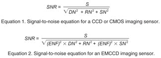
A calculation of SNR can be made based on its definition (signal
(S) divided by total noise), while using the variables of signal (incident photon
number multiplied by the quantum efficiency (QE) of the device), read noise (RN),
dark noise (DN) and shot noise (SN). Equation 1 uses these variables in the standard
signal-to-noise equation.
The equation also contains variables that are present in both
CCDs and scientific-grade CMOS cameras and, thus, can be applied to both. However,
for an EMCCD sensor, another noise source must be taken into account. Electron multiplication,
the EMCCD’s major advantage, dramatically improves its already low read noise,
but noise in the electron multiplication gain contributes an excess noise factor
(ENF) of ;1.4, as shown in Equation 2.2
Standard scientific-grade CCD cameras exhibit Gaussian noise.
However, spurious events also can occur in EMCCDs and can slightly skew the noise.
These events are small enough to be typically ignored in SNR equations but, nonetheless,
were taken into account in this paper’s SNR calculations (as part of the dark
noise component).
Scientific-grade CMOS sensors also display additional random telegraph
noise, which significantly skews the noise distribution to higher values.3 As a
result, the skewed noise distribution of a CMOS sensor can have as many as a third
of its pixels outside the normal Gaussian distribution. However, to simplify calculations,
a normal Gaussian noise distribution was assumed for the scientific-grade CMOS calculations
in this article. Consequently, the scientific-grade CMOS noise would be higher,
and its SNR values would be even worse, in reality.
That being said, because signal is dependent upon the number of
photons, a range of SNR values can be calculated as the number of photons added
to a detector is incrementally increased. Using EMCCD attributes from Photometrics
and scientific-grade CMOS data from marketing literature, such calculations were
made, and the values graphed in Figure 1, which demonstrates that the EMCCD outperforms
the scientific-grade CMOS in terms of SNR at the lowest light levels, up to a crossover
point at ;10 photons.
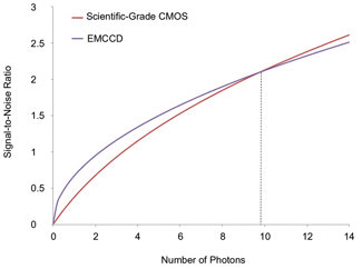
Figure 1. Oversimplified graph
comparing EMCCD and scientific-grade CMOS for various numbers of incoming photons.
Signal-to-noise ratios were calculated using Equations 1 and 2 and combined technical
values from marketing literature and Photometrics EMCCD datasheets. The EMCCD shows
higher performance over the CMOS at extremely low light levels up to a 10-photon
crossover. Note: Dark current was assumed as zero for both, as integration time
has not been taken into account. Images courtesy of Photometrics.
Camera and sensor manufacturers often use data such as the SNR
versus the number of photons to compare camera performance. However, there is a
significant problem in using the number of photons (a relatively abstract variable)
when it comes to comparing data for microscopy applications. The graph in Figure
1 allows comparison of one sensor with another if it is assumed that the number
of photons hitting each pixel would be the same for both detectors.
However, in the arena of light microscopy imaging, this is simply
not the case (Figure 2); e.g., EMCCD and scientific-grade CMOS sensors have different
pixel sizes, and an image projected equally upon both sensors would project various
numbers of photons per pixel for each camera. In other words, each smaller 6.5-μm
scientific-grade CMOS pixel would capture a smaller fraction of an image than each
larger EMCCD pixel. The effect is demonstrated in Figure 2. The smaller scientific-grade
CMOS pixels thus would each receive fewer incident photons and have a resulting
lower signal than the EMCCD. When such data is input into the standard signal-to-noise
equation, the lower signal also produces a lower SNR.
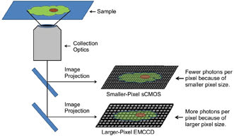
Figure 2. Comparison of light captured
using EMCCD and scientific-grade CMOS sensors. Both sensors are attached to the
same microscope, projecting the same image size on both sensors. However, the amount
of light captured per pixel will be less for the scientific-grade CMOS with smaller
pixels, compared with the EMCCD with larger pixels.
A more accurate graph of SNR data would take the pixel area into
account when calculating SNR. To do this, the number of photons per square micron
– i.e., photon density – can be used. Photons per square micron is
a measure of how the light image is spread as it is projected onto a microscope’s
imaging port. It should be identical to whichever sensor is attached to that microscope’s
imaging port, assuming identical optics, which is usually the case in experimental
light microscopy.
The number of photons hitting a pixel now can be calculated by
multiplying the photons per square micron by the square micron pixel area in a sensor.
That number then can be used to calculate the signal and the SNR, as shown in Figure
3. Note that this more realistic consideration of the effect of pixel size eliminates
the crossover completely, with the EMCCD showing a higher SNR at all photon numbers.
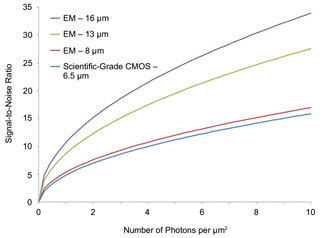
Figure 3. Graph comparing scientific-grade CMOS and EMCCD sensors
as a function of incident photons per square micron. Specifications from scientific-grade
CMOS marketing literature and EMCCD datasheets were used in the calculations. Graphing
versus photons per square micron accounts for increased signal collection with increasing
pixel size. Accordingly, all three EMCCD sensors show higher performance than the
scientific-grade CMOS sensor.
This more experimentally applicable parameter – photon density
(used in Figure 3) – is nonetheless still essentially fixed for a given optical
system in terms of collection efficiency, magnification and throughput of the optics
used because these parameters are not easily adjusted without changing the optical
system itself.
Illumination source intensity is potentially adjustable, but adjustment
can be difficult and generally only unidirectional – reduction from a maximized
intensity. Therefore, after accounting for actual pixel size and appropriating the
correct number of photons per pixel, the next real parameter that researchers would
typically use to optimize their images would be exposure time. Furthermore, when
such a comparison is made in terms of SNR, it is also important to take dark current
into account and thus use all parameters in SNR Equation 1.
Under realistic conditions
For a true comparison between scientific-grade CMOS and EMCCD
technologies, more realistic experimental conditions must be considered. In the
following study, integration time, a parameter commonly adjusted in experimental
applications to optimize signal, is used. To translate this parameter into a signal
and then an SNR, other variables are assumed in a realistic system.
In this case, the fluorescence from a sample of enhanced cyan
fluorescent protein (ECFP) is calculated as it is collected through a 60x objective
and projected onto a scientific-grade CMOS and three Photometrics EMCCDs (back-illuminated
Evolve 512 and Cascade II 1024 and the front-illuminated Cascade 1K). Note that
the Evolve 512 and Cascade II 1024 EMCCDs have QEs greater than 90 percent, while
the Cascade 1K’s QE is only 62 percent.4,5,6
ECFP’s molecular brightness, the collection solid angle
of the objective, the optical throughput, the pixel size and other realistic parameters
are used to calculate signal and then SNR as a function of integration time. A comparison
of the three Photometrics EMCCDs with the scientific-grade CMOS in rolling- and
global-shutter-readout modes is graphed in Figure 4, which shows that the scientific-grade
CMOS sensor’s SNR numbers never would reach the two back-illuminated EMCCDs’
SNR values, even at extensive integration times. This difference is the result of
the superior dark current, the read noise and the quantum efficiency, as well as
the larger pixel size of the EMCCDs. Also, the Cascade 1K shows favorable results
compared with the scientific-grade CMOS, with a higher SNR over the entire region.
And, as a result of its associated large dark noise, the global shutter mode of
the scientific-grade CMOS produces a tremendously lower SNR than all three EMCCDs,
over all exposure times.
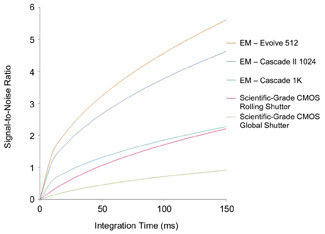
Figure 4. Graphed SNRs as a function of integration time for scientific-grade CMOS
and three Photometrics EMCCDs. The SNR values were calculated based on scientific-grade
CMOS literature and on Evolve 512, Cascade II 1024 and Cascade 1K EMCCD datasheets.4,5,6
The scientific-grade CMOS operated in either mode shows lower performance than even
that of the front-illuminated Cascade 1K EMCCD.
Microscopic Imaging
One final comparison of EMCCDs to scientific-grade CMOS sensors
is made in Figure 5. Here, a deeply cooled scientific-grade CMOS with lower dark
current is compared with the same three Photometrics EMCCDs and the uncooled scientific-grade
CMOS used in Figure 4. The results are similar to those in Figure 4, again showing
higher SNR values for the EMCCDs than the cooled and uncooled scientific-grade CMOS
sensors.
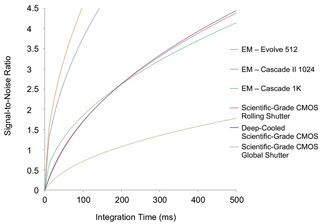
Figure 5. Graph comparing deeply cooled and uncooled scientific-grade CMOS sensors
and three Photometrics EMCCD sensors versus integration time. SNRs were calculated
using marketing literature and EMCCD datasheets. The cooled scientific-grade CMOS
shows similar numbers to the uncooled scientific-grade CMOS because its lower dark
noise is offset by its slightly higher read noise. The EMCCDs
outperform both in rapid imaging.
The reason for the similar results is that, although the deeply
cooled scientific-grade CMOS sensor has associated noise and a lower dark current
than the scientific-grade CMOS sensor, its read noise is slightly higher, producing
nearly overlapping curves for the two scientific-grade CMOS sensors. Indeed, the
uncooled scientific-grade CMOS actually shows slightly improved performance compared
with the deeply cooled scientific-grade CMOS at shorter integration times –
the result of having a lower quoted read noise than the cooled one. Therefore, in
the low-light-imaging regime, the cooled and uncooled CMOS sensors deliver similar
performance, which is below that of the three EMCCDs studied.
Visualizing SNR differences
Although Figures 3, 4 and 5 demonstrate the improved performance
of EMCCDs over scientific-grade CMOS sensors under low-light conditions, it is easier
to visualize the advantage by comparing biological images whose quality reflects
their differing SNRs. Figure 6 shows images of fluorescently labeled bovine pulmonary
artery endothelial cells that would be seen using the four cameras graphed in Figure
5 at 46-ms exposures and their associated SNR values after normalized scaling and
cropping to the same view. A comparison of the images shows the improved appearance
that accompanies the higher SNR values achieved by EMCCDs over the scientific-grade
CMOS at low light.

Figure 6. Comparison
of biological images that would be visualized with three EMCCDs and a scientific-grade
CMOS sensor with given SNRs. It is apparent that, under these low-light imaging
conditions, EMCCD images would have higher SNRs, with higher quality and easier
visualization. At higher light, the difference between Evolve 512 and CMOS images
would be even greater. (See Figure 4.)
Front-illuminated EMCCDs with midrange quantum efficiency, such
as the Cascade 1K, and high-quantum-efficiency back-illuminated EMCCDs, such as
the Evolve 512 and Cascade II 1024, all outperformed the cooled and uncooled scientific-grade
CMOS sensors under low-light experimental circumstances. The data even indicate
little real advantage from cooling the sCMOS cameras.
The advantage of the EMCCDs’ higher SNR values over the
scientific-grade CMOS was further illustrated by an associated improvement in image
appearance. It is evident through this study that in choosing an optimum sensor
for an application, how the sensors would perform within the optical system under
realistic experimental conditions should be considered.
Meet the authors
James R. Joubert is an applications scientist at Photometrics
in Tucson, Ariz.; e-mail: jjoubert@photometrics.com. Deepak K. Sharma is director
of product management at Photometrics; e-mail: dsharma@photometrics.com.
References
1. J.R. Janesick (2001). Scientific charge-coupled devices. SPIE
Press, Bellingham, Wash., pp. 3-22.
2. J.B. Pawley (2006). Handbook of biological confocal microscopy,
3rd ed. Springer, New York, pp. 76-79.
3. P. Martin-Gonthier et al (2010). Custom transistor layout design
techniques for random telegraph signal noise reduction in CMOS image sensors. Electronics
Letters, Vol. 46, pp. 1323-1324.
4. Photometrics Evolve 512 datasheet (http://www.photometrics.com/products/datasheets/evolve_512.pdf).
5. Photometrics Cascade II 1024 datasheet (http://www.photometrics.com/products/datasheets/CasII1024.pdf).
6. Photometrics Cascade 1K datasheet (http://www.photometrics.com/products/datasheets/1K.pdf).