With the large variety of beamsplitters available, the designer needs to take many factors into consideration. This article and its illustrations will go a long way toward making the correct choice less of a risk. All curves show typical performance.
CVI Melles Griot
Plate beamsplitters
Plate beamsplitters consist of a thin plate of optical crown glass with a different type of coating deposited on each side. The first surface is coated with an all-dielectric film having partial reflection properties over either the visible or the near-infrared spectrum. The benefit of this type of coating is that it has low absorption, typically 0.5 percent for a 50/50 splitter at 45°. The second surface has an antireflection coating optimized for 45°.
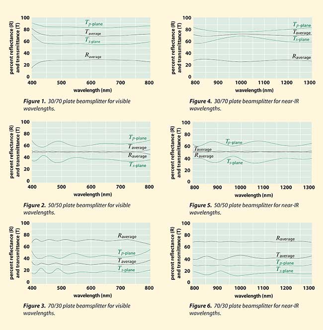
The transmittance and reflectance curves shown in Figures 1 through 6 are for unpolarized inputs at an angle of incidence of 45°. As can be seen from the p- and s-polarization components of the transmitted beams, these beamsplitters are highly polarization sensitive. For clarity, only the average polarization reflectance curve has been presented.

Nonpolarizing plate beamsplitters
Nonpolarizing plate beamsplitters have been designed for use in situations in which the polarization characteristics of the incident laser radiation must be maintained in the reflected and transmitted beams. They may also be used to obtain a 50/50 split in laser energy (within tolerances) regardless of the polarization state of the incident beam. Such performance cannot be expected of other plate beamsplitter coatings since they are extremely polarization sensitive.
Plate beamsplitters have a number of advantages over cube beamsplitters. Because they are devoid of optical cements that can absorb light energy, they can withstand significantly higher levels of laser power without damage. This is an important consideration when using moderate- or high-power lasers. Plate beamsplitters are also significantly smaller and lighter than their cube counterparts. In any application where size and weight constraints exist, plate beamsplitters are an option that should not be overlooked.
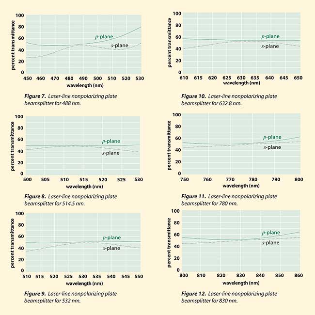
The beamsplitter coating for these products is deposited on one side of a 3-mm-thick BK7 plate. The reverse side is coated with an antireflection coating whose reflectivity is only 0.5 percent at an angle of incidence of 45°. At their specific laser line wavelengths, these coatings reflect 50 ±5 percent of the incident radiation. When an unpolarized beam is incident on these coatings, the s- and p-components of the reflected (and the transmitted) beam are matched to within 3 percent. Because both the beamsplitter and antireflection coatings are all dielectric in composition, they have negligible absorption. These plate beamsplitters are designed for specific laser wavelengths (Figures 7 through 12).

Long- and short-wavelength pass beamsplitters/filters
Dielectric coatings acting as edge filters are very useful for many types of applications. Edge-filter coatings consist of modified λ/4 stacks. All dielectric in construction, their absorption is negligible.
The edge filters described here are of both the short-wave- and the long-wave-pass varieties. They are wavelength-dependent beamsplitters, designed to be used at 45°. In the case of the long-wave-pass filter, the longer wavelengths are transmitted and the shorter wavelengths are reflected at 90° to the incident and transmitted beams. The opposite is true in the case of the short-pass design.
Both of these beamsplitters/filters have their 50 percent edge centered around 700 nm (Figures 13 and 14). They are both ideal for separating short-wave diode laser radiation from visible light. In addition, the long-wave-pass filter has high transmission out to 1600 nm, making it suitable for the longer wavelength telecommunications diodes.

Long-wave-pass beamsplitters/ filters may be fabricated from BK7 substrates and coated on both sides. The front surface is coated with an edge transmission coating that reflects light in the 550- to 650-nm range and transmits from 760 to 1600 nm. The rear surface is coated with a broadband antireflection coating. They should be used at incidence angles of 45° ±5°.
Short-wave-pass beamsplitters/filters also consist of a BK7 substrate with a rear-surface broadband antireflection coating. The front-surface coating transmits visible light (450 to 650 nm) and reflects 760- to 850-nm wavelength radiation. They should be used at incidence angles of 45° ±5°.
Cube beamsplitters
Cube beamsplitters have several advantages over plate beamsplitters and are widely used for a variety of reasons. These are rugged beamsplitters that are easy to mount and are ideal for beam superposition applications. This type of beamsplitter deforms much less when subjected to mechanical stress than does a plate beamsplitter. Most of the unwanted reflections from a cube beamsplitter are in the retrodirection and do not contribute to ghost images. The coating is very resistant to degradation with time because it is sealed within the body of the cube.
If cube beamsplitters are used in convergent or divergent portions of an optical beam, they will contribute substantial amounts of unwanted aberration. This can be avoided or minimized by using these components only with collimated or nearly collimated beams. Conjugate distances that include cubes, therefore, should be long. Alternately, other elements of the system can be designed to compensate for any aberrations introduced by the cube in a noncollimated beam.
Cube beamsplitters consist of matched pairs of identical right-angle prisms with their hypotenuse faces cemented together. Prior to cementing, a partial reflection film is deposited onto one of the faces. For best results, the incident beam should be on one of the faces of this prism. All cube beamsplitters should be antireflection-coated on all four faces to minimize ghost images.
Each of the following coating types has its particular merits and limitations, so your selection should depend on the intended application.
Hybrid partial-reflection coatings
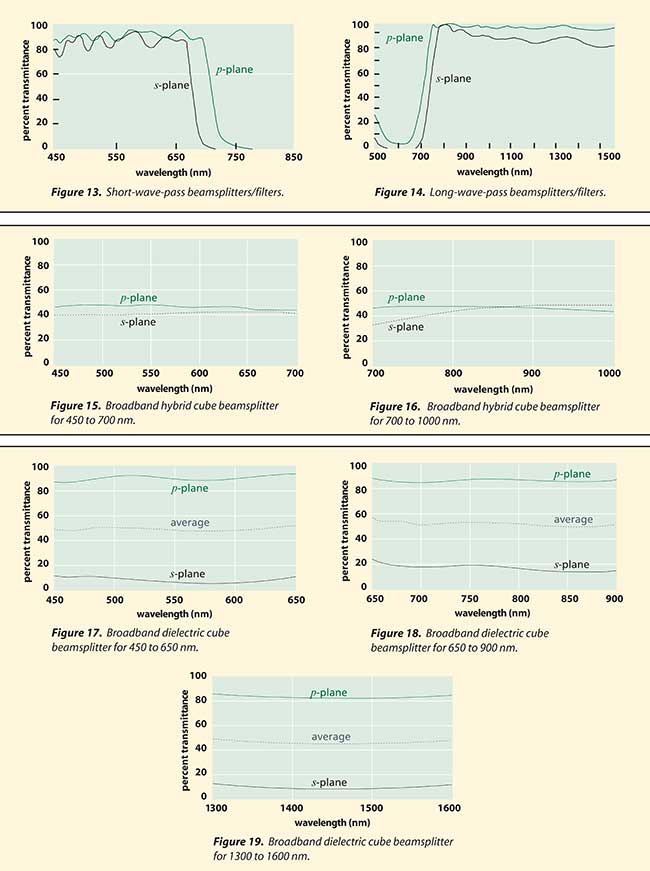
Hybrid, metal-dielectric coatings combine the benefits of both metals and dielectrics to produce a moderate-absorption beamsplitter with little polarization sensitivity. Typically, absorption is about 10 percent, while reflection and transmission are approximately 45 percent, with the s- and p-polarized components within 10 percent of each other. The broadband spectral flatness of these beamsplitters makes them ideal for wavelength scanning instruments (Figures 15 and 16).
Another advantage of these hybrid coatings is that they are fairly insensitive to changes in the angle of incidence. Although the cube beamsplitter configuration usually causes the angle of incidence to be 45°, this angular invariance in the performance has the advantage of making these beamsplitters chromatically neutral for convergent or divergent beams.
Broadband partial-reflection coatings
Broadband partial-reflection coatings provide a high degree of efficiency. There is negligible absorption in the coating and the reflected and transmitted components have almost equal intensity over a broadband wavelength range when averaged over p- and s-polarizations. They are, however, extremely polarization-sensitive, with the s- and p-components differing by as much as 70 percent. Care should be taken when using these broadband beamsplitters to consider polarization implications for the optical system into which they are to be integrated.
Broadband partial-reflection coatings are available for the visible spectrum (450 to 650 nm), the laser diode short-waveband (650 to 900 nm), and the laser diode telecommunications waveband (1300 to 1600 nm) (Figures 17 through 19).
All-dielectric nonpolarizing coatings
This range of cube beamsplitter coatings is intended for those applications where polarization effects must be kept to an absolute minimum. Unlike the hybrid coatings, these dielectric coatings are designed for high performance at specific wavelengths, where they easily exceed the performance of any other available cube beamsplitters. Being totally dielectric, they have negligible absorption.
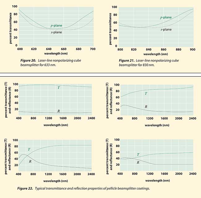
At the design wavelength, each of these beamsplitters reflects 50 ±5 percent of incident light. The s- and p-components of the reflected (and therefore transmitted) beam differ by less than 5 percent (i.e., each is within ±3 percent of the average polarization performance).
Pellicle beamsplitters
A pellicle beamsplitter is made of a high-tensile-strength elastic membrane, stretched like a drum-head over a black anodized flat metal frame, and bonded to the precision lapped edge of this frame. The membrane has a thickness of 5 µm or less, so that the separation of the primary and ghost images at a 45° angle of incidence is only about 7 µm, making them indistinguishable. Because the membrane is so thin, pellicle beamsplitters have some advantages over plate beamsplitters: Chromatic and spherical aberration in converging beams is negligible, absorption is very low and ghost image problems are virtually eliminated.

Uncoated pellicles transmit about 92 percent of incident radiation and reflect about 8 percent throughout the visible and near-infrared spectral regions. The membrane material, nitrocellulose, does exhibit absorption in the ultraviolet and in the infrared beyond 2 µm. In beamsplitting applications, coatings are deposited on one side of the membrane. The graphs in Figure 22 show the transmission and reflectance properties of these coatings. In convergent light, low-contrast interference fringes appear because of interference between reflections from the front and rear surfaces of the membrane. Because the reflectance of the metallic-coated surface far exceeds that of the uncoated surface, the visibility or contrast of these fringes is very low. Pellicles are often applied to situations in which the light is uncollimated.
Care should be taken in mounting pellicle beamsplitters because the mounting frame is easily deformed by stress. It also should be noted that pellicle beamsplitters are particularly sensitive to acoustical disturbances. To avoid transient wavefront distortions, they should be isolated from severe acoustical noise. Pellicle surfaces must not be touched and must be cleaned only with a gentle flow of clean, dry air.