
Amid the Drive to Improve Automotive Safety, Thermal Imager Design Innovation Soars
Regulations aimed at improving automotive and pedestrian safety are driving the optimization of size, weight, power, and cost parameters in thermal imaging systems and equipment.
By Wade Appelman
The use of thermal imaging in defense operations traces back more than 50 years.
In the late 1960s, the earliest iterations of thermal imagers deployed in this sector used cryogenically cooled image sensors. Ten years later, systems using uncooled microbolometer arrays further advanced thermal imaging technology toward ubiquity. Today, the military and defense sectors are widely recognized as the most prominent adopters of thermal imaging solutions.

Courtesy of OWL AI.
The defense industry has sought for
decades to optimize the size, weight, power, and cost (SWaP-C) metric; it has used it to gauge both the viability and, as a result, the prevalence of the solutions
it chooses to implement. Commercial
sectors have also adopted SWaP-C,
applying it to a variety of electronic
devices such as radios, cameras, and
sensors in cellphones.
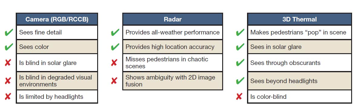
Imaging modalities used to obtain and deliver automotive images offer distinct advantages — as well as limitations. The use of thermal imaging resolves gaps left by other modalities. RCCB: red-clear-clear-blue. Courtesy of OWL AI.
Developers of commercial vehicles are among the most recent groups to emphasize the need to meet SWaP-C goals. In this sector, devices that meet SWaP-C goals must operate in environments that are often more demanding than those faced even in defense applications.
The rule issued last year by the U.S. National Highway Traffic Safety Administration (NHTSA), referred to as FMVSS No. 127, is the latest example of this trend. It requires essentially all cars and light trucks starting with model year 2029 to include pedestrian automatic emergency braking (PAEB) systems that operate day and night, year-round, and in adverse weather conditions.
Successful implementation of this mandate will require detecting pedestrians in the dark, in the rain or snow, and at distances of up to 100 m, as well as during the daytime when looking into the sunset. Though several demonstrations have shown that thermal imaging is the only way to provide the data quality needed for reliable detection in all these situations, optimizing thermal imaging solutions remains a challenge.
Today, the goal is to devise a way to apply SWaP-C to thermal cameras with sufficient performance to meet NHTSA requirements, so that thermal imaging can be successfully used in automotive systems.
Operating requirements
To produce thermal images near room temperature (~300 K), two electromagnetic wavelength bands in which the atmosphere is transparent can be detected: the midwave infrared (MWIR) band, covering 3 to 5 µm, and the longwave infrared (LWIR) band, covering 8 to 14 µm.
Both bands can produce images using either cooled or uncooled sensors, though uncooled sensors do not provide a sufficient signal-to-noise ratio in the MWIR band for images of the necessary quality. As a result, to minimize cost and complexity, almost all nondefense applications use uncooled microbolometer cameras operating in the LWIR band.
Thermal images acquired in the LWIR band are also the highest-quality images that can be obtained in obscured conditions such as rain, snow, fog, and smoke. In the LWIR, pedestrians — the focus of the NHTSA rule — can be imaged by their own thermal radiation, while most inanimate objects fade into the background. Even on hot days, with natural or artificial backlighting, or amid other obscurants, LWIR thermal images maintain contrast between people and their surroundings.
Thermal imaging using cryogenically cooled area arrays spread in the 1970s, followed by uncooled microbolometer arrays in the 1980s. The highest-performance thermal cameras in use today are still cooled, but smaller, cheaper uncooled cameras make up the vast majority of units in service. Unsurprisingly, the highest-performance thermal cameras currently on the market are also the most expensive. The cost of uncooled cameras is closely related to requirements for spatial resolution, as well as thermal resolution, which is the smallest difference in temperature in the scene that the camera can reproduce.
Defense systems often require a spatial resolution of 1024 × 768 pixels or more, with a thermal resolution typically <40 mK (1 mK = 0.001 °C). Costs in the tens of thousands of dollars are typical for such cameras. For context, medical applications may require imagers to achieve a spatial resolution of 256 × 320 pixels while still requiring thermal resolution <50 mK for accurate skin temperature measurements. Such a system, despite the comparatively modest spatial resolution, still costs thousands of dollars. Hand-held cameras, such as those used to monitor buildings for heat leaks, may need only 60 × 80 pixels and less demanding thermal resolution of 1 °C. These cameras often cost only hundreds of dollars.
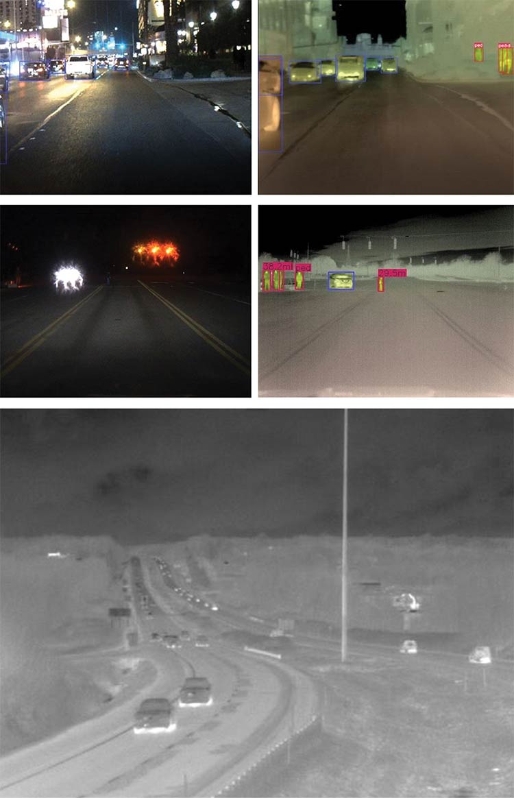
Thermal images reveal objects of interest, including pedestrians and other vehicles, even in the presence of various obscurants. Courtesy of OWL AI.
Analysis of the automotive PAEB requirement shows that the horizontal pixel count must be 1000 or more, and the thermal resolution must be no more than 40 mK. This is clearly in the range of defense system performance, especially considering the operating environment.
But, to make automotive installation
viable, the cost can rise to only ~1% of that of the defense equipment.
Rethinking for SWaP-C
Meeting this objective — a horizontal pixel count of 1000 or more and a thermal resolution of 50 mK or less — requires a complete rethink of thermal camera architecture and fabrication. The size of the automotive market justifies this effort, especially since successful camera and sensor designs and rollouts would open up downstream high-volume markets. Among other applications, the possibilities span nighttime home security, real-time thermal inspection on manufacturing lines, day-and-night guidance of autonomous vehicles, and even integrated thermal imaging in cellphones.
Fortunately for designers, several characteristics common to current thermal cameras are promising candidates to aid in the quest for SWaP-C improvement. The architecture of the common microbolometer sensor is one approach that systems designers can reapply. These components were initially proposed in the 1970s and have undergone minimal change in the 30 years since Honeywell patented the use of vanadium oxides as the resistive element1.
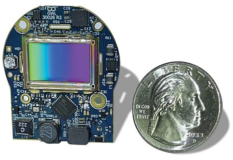
Complete digital functionality is contained in the sensor chip, meaning that only power conditioning and an external interface are needed to create a complete camera with 12-V direct current input and serial digital video output. Courtesy of OWL AI.
To build an uncooled thermal sensor, an array of microbolometers with a pitch of 20 µm or less is fabricated on a silicon wafer using today’s available microelectromechanical systems (MEMS) technology. This wafer is then thinned and bump-bonded on top of another wafer. This additional wafer, called the readout integrated circuit (ROIC), contains the circuits necessary to power the microbolometers and detect their resistance, which indicates temperature. The micro-
bolometer information readout is a sequence of analog signals, and the off-chip circuits further process these signals.
The temperature of the sensor substrate — both the offset of the signal and the differential change in signal resulting from temperature differences in the object being imaged — strongly influences
microbolometer readings. Therefore, the use of nonuniformity correction is required. The nonuniformity correction process requires substantial processing power and memory. It also uses much of the dynamic range of the digital signal,
which increases all the individual SWaP-C factors. Additionally, since this correction is practical only using digital arithmetic, the ROIC output must be converted to digital form.
The present challenge therefore is to counteract this effect through intuitive sensor design processes.
Realizing SWaP-C goals
In uncooled thermal imaging, it is necessary to reconsider numerous legacies to achieve the goals of a small, high-performance, low-cost imager. These include the structure of the microbolometer array, the configuration of the readout circuitry, the methods for implementing image data corrections, and the architecture of the camera electronics.
The multistep process required to meet the necessary SWaP-C goals deriving from the updated NHTSA requirements starts at the wafer level. The conventional microbolometer sensor comprises two wafers stuck together with ball bonds, whereas adopting a different set of fabrication processes enables a one-wafer assembly. In this approach, the ROIC is fabricated first, and the microbolometer array is then essentially grown on the top surface of the ROIC. This process increases yields and reduces costs by eliminating the bonding step.
By reconceptualizing the circuitry, the ROIC can effectively be fabricated to function as a compact digital component. It can be further optimized to perform nonuniformity correction.
Eliminating the provision for bonding pads opens another possibility: More area is now available under each individual microbolometer. And because the sensor is intended for automotive use and is temperature-compliant, engineers can adopt fine-line digital fabrication processes. The resulting circuitry is compact enough to eliminate the circuit areas that surround the microbolometer array in analog devices. The image on this page shows that the whole available area can be filled with microbolometers.
It is ideal to perform the digitization
process slowly to minimize power requirements. The ROIC in this design has enough space available to support a dedicated delta-sigma analog-to-digital converter under each pixel, which can subsequently be fabricated. The benefit of this design is simple: Analog-to-digital converter architectures feature access points for inserting nonuniformity correction offset and gain correction data,
so that the signal from the ROIC is already corrected. This removes the need for external processing and avoids the
resulting negative effects on signal quality2.
In conventional thermal cameras, it is necessary to periodically reacquire the nonuniformity calibration data, due primarily to drift in the sensor temperature. To acquire this data, the external image must be excluded. This task is most often accomplished by closing a mechanical shutter long enough for the sensor to stabilize in the dark. The shutter increases all SWaP-C measures and, critically,
interrupts the flow of image data — which is not tolerable in automotive systems implemented to protect pedestrians.
With a digital ROIC, however, temperature calibration data acquired during sensor testing can be permanently stored. Further, the sensor can include sufficient dummy sensor elements to provide real-time temperature profile data to the ROIC controller. This combination permits nonuniformity calibration to be updated as often as necessary while the sensor is active, which prevents the system from interrupting the image data flow.
Now that most of the circuitry needed to operate the sensor and produce corrected digital image data is contained in the sensor itself, the support circuitry need only include power conditioning and an appropriate external digital interface. This is easily addressed, since a complete thermal camera can be fabricated on a single small board, and the power conditioning component count is lower when the sensor is included on a circuit board with other functional chips.
A final advantage involves the use of the current class of high-speed serial digital interfaces. These components directly contribute to controlling the SWaP-C parameters and further enable the use of a single lightweight cable carrying power, control commands, and camera digital image data. The image on page 39 shows a module that requires only a housing with a small heatsink at the rear and a mount for the lens.
Deployment considerations
To preserve the SWaP-C improvement benefits when incorporating a module — such as that described — into systems, a user or systems integrator must carefully consider the application requirements. In the automotive PAEB case, the frame rate of the images must be high enough to allow rapid and continuous detection of pedestrian location; 30 Hz or higher frame rates are indicated. However, automobile manufacturers are often unable to manage the export licensing paperwork required to ship fast, high-resolution
thermal cameras around the world.
As a result, the module must include another feature: It must operate only in the intended installation. Any attempt to operate the module outside the vehicle must fail.
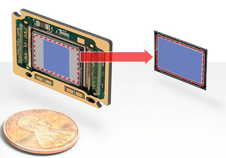
Traditional video graphics array microbolometer sensor implementations require space on the chip around the active area for support circuitry. The sensor described in this article uses the entire chip surface, enabling megapixel resolution in the same area. Courtesy of OWL AI.
This is an important consideration, since with a digital ROIC, a camera startup can be designed to initiate only upon the receipt of an identification command from the vehicle. Even if the sensor is removed from the module, the command is still needed to make it run because the decoding operation is inside the sensor.
This function is also useful when the modules are deployed in drones: Cameras retrieved from downed drones will not function without commands from the
correct drone operator. The benefit is that any captured thermal camera will be
unusable by adversaries or unintended users.
Optics
No matter the imager type, the camera optics — namely the lens — are components that may traditionally be even more expensive than the camera electronics. In the case of thermal imagers, LWIR optics are historically made from germanium and a few additional glasses that transmit in this band. These materials are expensive to obtain and fabricate. Further, the energy absorption of germanium increases with temperature. This undesirable quality can lead to thermal runaway under direct exposure to bright sources and erratic performance in situations in which the camera must operate over wide temperature ranges.
Two optical technologies are now contributing to decreased costs and, in some cases, size and weight. One, chalcogenide glasses, is less expensive and generally considered easier to fabricate than alternative materials. The second is the broadening availability of diffractive optical elements. These thin plates, which may also be composed of chalcogenide glasses, drive optical power and can
provide aberration corrections not achievable with traditional glass lens elements alone.
The SWaP-C pressure — from the same automotive markets that spurred new thermal camera designs through the previous decade — is only now beginning to emerge as a driver for lenses that incorporate these technologies. The high-definition camera module described in this article was conceptualized to implement all the factors in the SWaP-C suite. It is smaller and lighter than conventional thermal cameras due to the elimination of most support circuitry and the external shutter. Power consumption is significantly reduced, and the higher level of integration supports cost reductions in excess of 10×.
Future prospects
Improvements to both design processes and components are poised to open additional opportunities in multiple markets. Autonomous vehicles will benefit from affordable, reliable thermal-detection capabilities, improving navigation and safety. Drones, for dual use in defense and civilian applications such as agriculture, fire suppression, security, and facility
inspection, will benefit from low-cost, high-performance thermal imaging. Industrial inspection, including real-time thermal monitoring of both products and production machinery, will also become feasible.
Rejecting the design assumptions of the past and accepting the increased risks are fundamental to developing disruptive
products. At the same time, realizing success in offering thermal imaging to markets for which only unsuitable options previously existed makes the effort worth expending.
Meet the author
Wade Appelman is chief business officer at Owl Autonomous Imaging (Owl AI). He has led sales and marketing efforts for multiple venture-backed startups, with total exit valuations of $900 million. Prior to Owl, he was vice president of the depth sensing division at OnSemi and SensL; email: wadea@owlai.us.
References
1. R. Andrew Wood (Sept. 12, 1995). Use of vanadium oxide in microbolometer sensors. U.S. Patent No. 5450053A. U.S. Patent and Trademark Office.
2. F. Ataei and E. Petillli (Aug. 8, 2024).
Methods and systems for thermal image sensing. U.S. Patent No. 20240264003A1. U.S. Patent and Trademark Office.
/Buyers-Guide/Owl-Autonomous-Imaging/c33344