ADAM MULL, DATALOGIC AUTOMATION INC.
The world of industrial automation continues to advance technically. In the past few years, the machine vision industry has developed and introduced many new 3D methodologies, including time-of-flight analysis, projected pattern correlation, laser line/triangulation measurements and stereoscopic area-scan camera technologies. With the exception of low-resolution palletizer systems, few of these technologies have gained much traction. While some solutions have found specific niches in the market, most are hamstrung by one or more common problems.
Problems faced by traditional solutions
Ambient lighting — Both projected patterns, as well as laser-based methods, have diminished results in quality when other light sources are present. These methods calculate distance and shape by utilizing structured lighting. When structured lighting is in competition with any other light, the contrast is reduced, thus affecting overall performance and measurement accuracy.
Specular reflection — While laser line/triangulation methods have good resolutions, they typically fall short on shiny, reflective objects. Reflective surfaces often require specialized lighting to reduce blooming or glare due to the inherent reflective nature of the part’s material composition. Such reflective properties may disqualify them from most high-resolution, 3D scanning applications.
Occlusion — For many products and applications, inspection technologies that use only one camera will be limited in the ability to inspect the entire product due to visual blockages caused by other products, contours or features within the field of view. When multiple inspection samples are viewed at any angle in the same field of view — other than when viewed from directly above at a 90° angle — the foreground objects may appear to overlap the objects behind them. These obstructed portions of the background objects cause them not to be fully visible during the optical inspection process.
Low resolution — Today, there are some viable 3D solutions on the market, most of which are lower-resolution systems aimed specifically at robot guidance applications. The higher-resolution options on the market suffer from the first three problems addressed (i.e., ambient lighting, specular reflection and occlusion). The industrial automation industry has lacked a high-resolution solution that is robust enough to work on most common materials while still being able to deliver the precision needed to satisfy the most demanding applications.
Inspection algorithm capability — Having a good image is paramount to most of today’s machine vision applications. However, the software toolset that accompanies the system is a significant factor, not only in the quality and robustness of the final application and inspection results, but also regarding the speed at which applications can be developed and deployed. Some of the more familiar 3D software options lack the maturity required to fully appreciate the respective system’s inspection potential, while other software takes an extraordinary amount of time to fully deploy, making it difficult to create applications in a timely manner.
Line-scan technology
There are differences between area-scan camera and line-scan camera technologies; it’s important to understand these differences. An area-scan camera provides the typical “framed” image. It takes a single image of an area and it does so at the same point in time. This is the technology behind point-and-shoot, consumer-market cameras, as well as smartphone cameras. The matrix of pixels captures an entire scene when the button is pressed.
In contrast, a line-scan camera only acquires a single row of pixels at a time — it captures only a “slice” of the object, one row at a time, and constructs the image as the object passes by the camera. When set up correctly, this method allows for fast image acquisition and avoids lens distortions and occlusions from other objects. Reflections and ambient light have limited influence on line-scan images due to the intensity of the primary light source.
A typical line-scan system configuration includes a camera, lighting and form of motion, as well as an encoder to send high-frequency triggers, all of which serve to create the slice-by-slice scans. Additionally, line-scan technology lends itself nicely to cylindrical objects and web inspections due to reduced distortion created by the “slicing” effect on parts.
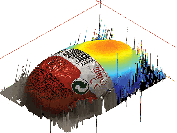
Datalogic Automation’s 3D stereo line-scan system, the I-105, addresses common stereoscopic imaging roadblocks while producing color images (Figure 1). The system’s name is derived from its 105-mm field of view. Operating from a working distance of 173.6 mm, it functions at a 21.2 kHz frame rate and has a maximum transport speed of 0.63 m/s.

Figure 1. A foil-wrapped egg, shown with a color rendering and height map.
The system is composed of a single imaging sensor, split in half and shared by two lenses. The two lenses in the camera head acquire the same row of pixels. The camera then compares the two images and analyzes the disparity between the matched points — this is where the Z-axis height information is generated. By calculating how close or how far apart the matched points are, the camera can determine height with 7-µm accuracy.
The camera outputs a color image, a 3D point cloud and a 2D grayscale height map. Each image can be referenced and utilized by IMPACT software for viewing and performing different inspections. The suite is a set of drag-and-drop algorithms, and is used for creating machine vision programs and control panels. Additionally, there are a few options for visual rendering of the 3D point cloud, such as a true-color overlay or a smoothened grayscale overlay. The inspection program can be used to develop a human-machine interface.

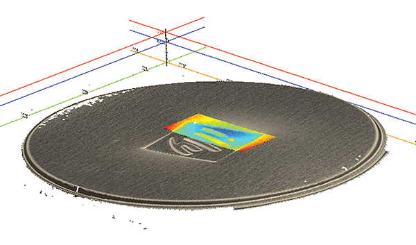
Figure 2. A virtually featureless, reflective metal surface, imaged with the I-105 system.
The 3D stereo line-scan system’s lighting is more refined than the
lighting used with area scan methodologies. It is intense enough to
overcome ambient light and only needs to be optimized over a single row
of pixels and not over an entire scene. Specular reflection is overcome
by using a specialized, diffused “cloudy day”
illuminator, which is a tube light specifically designed for line-scan applications. By applying uniform, even lighting over an object, hot spots and glare can be avoided (Figure 2). This opens the door to precision applications that cannot be solved with laser-based 3D solutions due to the specular reflection caused by laser illumination, which renders such a system an inferior scanning solution for this type of application.

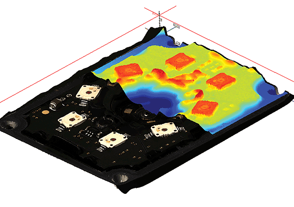
Figure 3. Datalogic Automation’s P-Series illuminator. This image showcases the I-105 system’s ability to capture color and fine detail, and to avoid occlusions while imaging a variety of materials.
The use of two line-scan cameras provides an unobstructed view of a contoured surface. Due to the object moving past the camera, there are fewer visual shadows or occlusions to hinder the inspection process. The entire surface can be constructed into a 3D point cloud (Figure 3). Used in tandem with the software, users can perform functions such as plane fitting, project to 3D, virtual camera, and point-to-plane measurements. Color images can be accessed in order to assist in classifying or sorting applications.
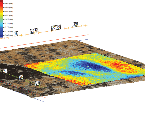
 Figure 4. A piece of ceramic tile with a region highlighted to demonstrate the sensitivity of the camera on a “flat” surface.
Stereo line-scan technology is a suitable alternative for integrators and machine builders that have had to pass on applications deemed unsolvable with traditional machine vision resources. The 3D tools allow the user to create reference planes and take precise measurements from the plane to numerous different regions of interest. Based upon the needs of the application, specified tolerances can then be set. These types of coplanarity inspections open the door to a new breed of machine vision solutions by allowing for precise, high-speed processing of 3D data.
This type of technology provides a systematic approach to stereo line-scan solutions by combining the cameras, processor, lighting and software. The combination of imaging components and software eases system integration and application development by restricting the parameters that often leach a significant amount of engineering time. Advancements in imaging technologies and methodologies help the industry overcome some of its most difficult challenges.
Meet the author
Adam Mull is a machine vision/laser marking system sales specialist at Datalogic Automation Inc. in Minneapolis; email: [email protected].