The basic fiber-based communications system consists of a laser transmitter which converts electrical data to intensity-modulated light, a fiber optic cable as short as a few meters or as long as 100-plus kilometers, and a photodetector that converts the information on the light back to an electrical signal.
Greg D. Le Cheminant, Agilent Technologies
An indicator of how well the entire system performs is a measurement called bit-error-ratio (BER). Acceptable BERs range from one error per billion to one per trillion bits transmitted. It is rare for a newly designed system to operate at these performance levels at initial turn on. Prior to system construction the individual elements must be characterized to determine their potential for proper system level performance. This article discusses analysis of high-speed transmitters with emphasis on waveforms.
Most transmitters for high-speed digital communications are laser based, although shorter, slower data rate systems may use light-emitting diodes. Several parameters are used to specify/qualify the performance of a laser transmitter: what is the spectrum of the transmitter signal, what is the strength of the signal, and how well does the signal carry information.
To determine how well a transmitter carries information, the time-domain waveform is analyzed. The waveform for a communication signal will look like a pulse train showing a pattern of ones and zeroes. However, rather than observe just a small sequence of bits, it would be useful to observe as many bits as possible to examine the overall transmitter performance. This is achieved with the eye diagram, where all the bit waveforms are superimposed on top of each other by triggering the oscilloscope with a clock signal that is synchronous with the data being measured.
Large separation needed
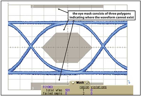
For error-free communications, the amplitude separation between the logic-one signal level and the logic-zero signal level should be large. An “open” eye diagram manifests this. Mask testing provides a quantitative way to measure how open an eye diagram is. In a mask test, polygons are placed on the eye diagram, indicating where the waveform may not exist (Figure 1). A laser signal that has no mask violations (signals that cross through any of the polygons) will be one that has a well-shaped eye diagram.

Figure 1. Eye diagram mask testing.
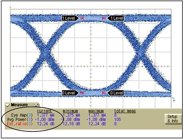
In addition to the relative opening of the eye, the absolute opening needs to be quantified. A parameter that indicates the separation between the mean one level and the mean zero level is optical modulation amplitude (OMA). On the other hand, extinction ratio is the ratio of the one level to the zero level (whereas OMA is the difference between the one and zero level).
Extinction ratio indicates how efficiently the electrical signal modulating the laser is converted to optical signal power. In the ideal case, very little power is consumed transmitting a zero. Low zero powers are indicated by high extinction ratios. Typical values of extinction ratio are 10 or higher. Note that as the extinction ratio becomes high, the one level and the OMA converge to the same value, and the average power is approximately half of the one level.
Eye diagram tests determine if the transmitter can be paired with a receiver and produce a working communications system. If the receiver’s perception of the waveform is critical, then it is important to find a way to do the mask test from the perspective of the system receiver. For many years, the concept of a reference receiver has been the foundation of standards-based optical transmitter tests. A reference receiver is an optical-to-electrical converter with a fourth order Bessel-Thomson frequency response whose –3 dB bandwidth is set to a frequency of 75 percent of the transmission data rate. For example, if the transmitter operates at 10 Gb/s, the reference receiver bandwidth will be 7.5 GHz. The reference receiver provides the test system the desired communications system receiver perspective. While a system receiver is not required to have a “75 percent of bit rate” bandwidth, this characteristic is a close approximation of the ideal receiver response for a nonreturn-to-zero (NRZ) waveform.
The bandwidth of a reference receiver will almost always remove high-frequency content of a waveform such as overshoot and ringing. The same signal, when viewed with a wider bandwidth receiver could easily have eye mask violations.
The use of a reference receiver may seem counterintuitive, because it can actually clean up a signal and yield a very well behaved eye diagram. This is where it becomes important to take a step back and remember the goal of testing. It is not to precisely characterize the behavior of the laser. Rather, the test is intended to determine how well the laser will interoperate with a receiver in a real communications system. System receivers will not have infinite bandwidth, so it makes no sense to test the transmitter as if it were communicating with a receiver that did. Instead, receivers often have just enough bandwidth to correctly differentiate a logic one from a logic zero. For an NRZ signal the ideal system bandwidth will be near 75 percent of the data rate, the bandwidth used by the reference receiver. Thus the test reference receiver provides a good representation of the signal from the perspective of a system receiver. Additionally, a reference receiver provides consistency in test. If everyone tests with a specific measurement system bandwidth, results should not vary between test systems. Vendors and their customers should get similar test results, as long as they use agreed upon receiver bandwidths in their test systems.
What is the basis for using the specific 75 percent data rate Bessel-Thomson design in the test system receiver? First, real system receivers will have limited bandwidth to optimize the signal-to-noise ratio at the decision circuit. It is then desirable to observe the transmitter waveform in a reduced bandwidth also. What should that bandwidth be? The lower the bandwidth, the lower the noise. However, if the bandwidth is reduced too much, there will eventually be inter-symbol interference, as the waveform takes longer to transition from one logic level to another. This results in waveform trajectories that begin to close down the eye. The lowest bandwidth that will not result in inter-symbol interference is at 75 percent of the data rate. This is the “Thomson” element of the filter.
Why use a Bessel-type filter design? The Bessel filter design achieves the best time domain response. That is, while its frequency domain characteristics are inferior to some filter designs in terms of its ability to suppress higher frequency signals, it has superior waveform performance with minimal eye diagram distortion (overshoot, ringing, etc.). Simply, the Bessel filter has constant group delay in the filter passband. At very fast data rates, it is difficult to produce an optical reference receiver that meets these ideal characteristics by combining electrical filters and high-speed photodiodes. This is why reference receivers are integrated into instruments dedicated to optical waveform analysis.
As speeds increase, it becomes more difficult to maintain the horizontal opening of the eye diagram. The result is similar to vertical eye closure. That is, receivers will have a more difficult time determining the logic level of bits. BER is then degraded. While vertical eye opening is reduced through noise, waveform distortion and attenuation, horizontal eye opening is greatly affected by the timing stability of the transmitted bits. Timing instability is commonly referred to as jitter.
Understanding jitter
Jitter, in its most basic definition, is the deviation of the edges of a data signal from their ideal positions in time. To understand why jitter can degrade BER, consider that a data receiver must set an optimum signal level and an optimum time to determine if a received bit is at a high or low logic level. The decision threshold is typically the center amplitude of the bitstream. The decision process degrades when the waveform has excess noise or distortion or is small in amplitude. The decision is ideally made in the time center of the bit. The decision process is degraded if the timing of the bits is inconsistent. A jitter-free signal would be one that has unvarying bit periods and edges that occur exactly at the expected times. This allows the receiver to make its logic decision far away (in time) from where bits transition from low to high levels or vice versa. If the receiver makes its decision near the transition (edge), the probability of the receiver making a mistake increases.

Figure 2. Extracting key transmitter parameters from the eye diagram.
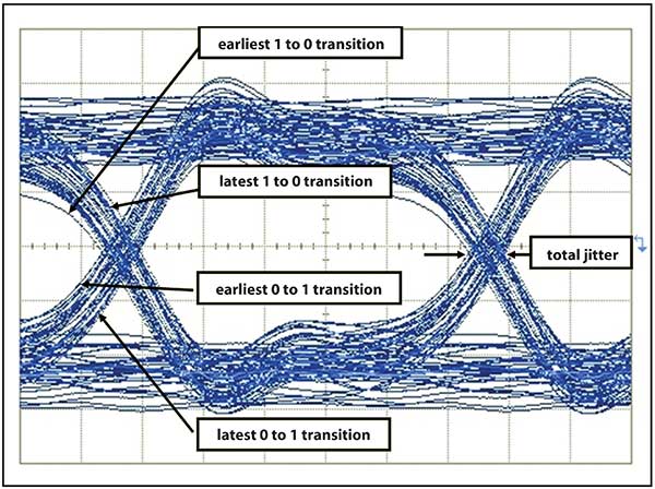
One can visualize jitter through the eye diagram (Figure 2). The eye diagram is a composite of all the bits from a data stream overlaid on a common time base. If the time base is defined by a jitter-free clock signal at the nominal data rate, some bits will slide to the left (early bits) or to the right (late bits) when there is jitter. This results in horizontal closure of the eye diagram. In real world systems, the most extreme displaced edges (those closest to the center of the eye, assuming the jitter magnitude is not extreme) occur least frequently. More frequently, edges will be located close to their ideal position (Figure 3). If this were jitter free, one to zero transitions would be tightly grouped, as would the zero to one transitions. But in this case, there is a noticeable difference between the earliest and latest bit edges.

Figure 3. Eye diagram for a transmitter with significant jitter.
As data rates increase, jitter problems tend to become more difficult. What might have been considered a small and tolerable time deviation at a lower data rate appears to be large and intolerable at high data rates since the bit period has become proportionally smaller. Measurement tools to accurately quantify jitter are required. In addition to quantifying jitter, methods that provide insight into the nature of jitter and its root causes become more important. System bit-error-ratio specifications at levels of 1E-12 and lower require the ability to quantify jitter at extremely low levels and probabilities. The analysis of jitter can be enhanced through segregating jitter into classifications aligned with fundamental root causes. The first two groupings are for jitter caused by random mechanisms (RJ) and jitter from deterministic mechanisms (DJ).
RJ is the jitter due to stochastic processes such as those that cause random fluctuations in oscillator/clock frequencies, which in turn cause data rates to fluctuate proportionally. Conversely, DJ is jitter that is due to predictable mechanisms. The DJ can be further classified into two subclasses. Some DJ will be due to how a transmitter performs (i.e., how jitter is produced) for different data patterns. This is data-dependent jitter (DDJ). Other elements of DJ will be deterministic, but uncorrelated to the data pattern. For example, switching power supply noise, which is periodic, but unrelated to the data pattern, can cause data clocks to deviate in frequency and lead to jitter of the data.
Some limitations
Optical waveforms are most often analyzed with sampling oscilloscopes, which have the widest bandwidths, a requirement for accurate analysis of very high speed digital transmitters. However, wide bandwidth has historically been accompanied by a relatively low data acquisition rate. This has significantly limited the capability of the sampling oscilloscope to a coarse view of the overall jitter of a signal.
Developments in sampling oscilloscopes have radically changed the jitter analysis capabilities available for very high speed transmitters. Jitter can now be decomposed into its random and deterministic components including periodic, intersymbol interference, subrate, and duty cycle distortion jitter classifications. The measurement process is incredibly fast due to advanced triggering capabilities that allow efficient analysis of long data patterns, which is essential for practical analysis of data dependent jitter.

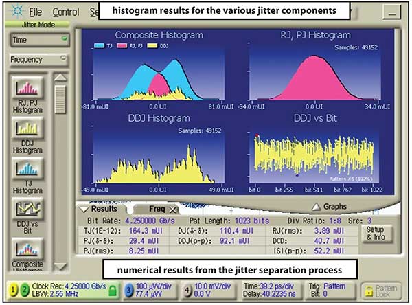
Figure 4. Jitter separation analysis of a 4.25 Gb/s signal.
Figure 4 shows the jitter analysis results for a transmitter operating at 4.25 Gb/s. The jitter of this signal has been decomposed into its constituent components. The individual jitter mechanisms can then be combined to predict what the aggregate jitter magnitude is to a 10E-12 probability, which can then be used to design system level jitter budgets that operate at low BERs.
Most communications systems are built around an industry standard. The standard in turn will have the minimal specification for the components that make up the system. A battery of tests, many that are based upon analysis of the eye diagram, are used to determine the viability of the transmitter to work in a complete system. As transmission speeds increase and bit periods shrink, in-depth analysis of timing stability (jitter) has gained importance in transmitter verification.