Spectrum Analysis for DWDM: New Instruments Meet the Challenge
Francis Audet, EXFO
As system and cable installers try to optimize their links, the preferred method has become high-speed DWDM. This demand for bandwidth has led to the development of new test and measurement instruments. Outside plant (OSP) customers and even component and fiber manufacturers are now looking for instruments that deliver laboratory-quality results and are still portable and rugged enough.
The wide-scale deployment of DWDM systems with high fiber counts and closely spaced channels has sped the development of a new generation of more powerful optical spectrum analyzers (OSAs). OSAs ensure proper system operation by measuring most of the parameters in a DWDM system, as well as characterizing individual optical components. They also can be used during the development, manufacturing, installation, commissioning and maintenance of optical networks and components.
Three types of OSAs are available, depending on the application: benchtop, mainly for DWDM component characterization; embedded, for incorporation in DWDM transmission systems; and portable, for system testing and characterization. Each has strengths and weaknesses depending on the application.
Design evolution
There are basically three designs, which are based on Fabry-Perot filters, Michelson interferometers or diffraction gratings. The choice of technology is largely dependent on size constraints, critical system operating requirements and the minimum mean time between failure (MTBF) acceptance.

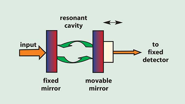
Figure 1. The Fabry-Perot interferometer design offers good spectral resolution but poor OSNR and wavelength range.
Fabry-Perot filter-based OSAs are becoming very popular in embedded systems where a Fabry-Perot filter is used as the tuning element. It consists mainly of two highly reflective parallel mirrors which act as a resonant cavity (Figure 1). The wavelength can be tuned by changing the mirrors' spacing. The disadvantage is a small wavelength range and a low optical rejection ratio (ORR) or optical signal-to-noise ratio (OSNR) value at 0.1 nm, 0.2 nm and 0.4 nm. However, its narrow spectral resolution is a major advantage. For embedded applications, the required MTBF is about 15 to 20 years.
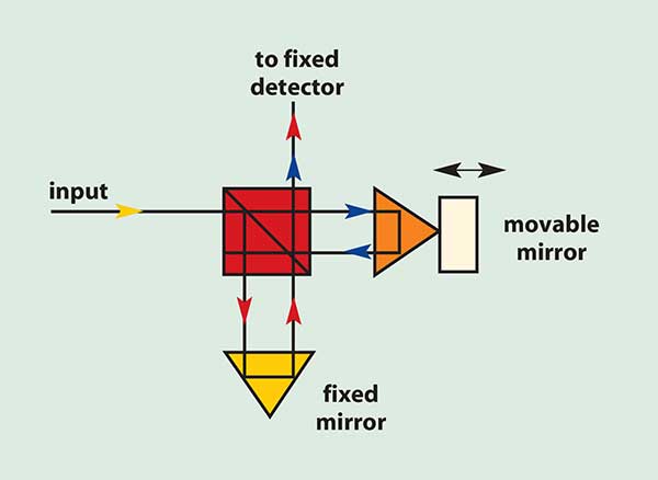
One version of the OSA commonly used for portable instruments is based on the Michelson interferometric method. In this design, the input signal is split into two paths by the beamsplitter. The beams are then reflected back by two mirrors, one fixed and one movable. The beams create sequentially constructive and destructive interference according to the different path lengths. The output electrical signal is mathematically analyzed using fast Fourier transform algorithms to reveal the input signal in a wavelength range (Figure 2).

Figure 2. The optical alignment of the Michelson interferometer design is resistant to shock but has a small dynamic range.
This design is weak in its ability to provide a large dynamic range and good spectral resolution. Furthermore, inadequate noise interference renders it incapable of making noise measurements. Limited to an ORR slightly over 30 dB, it is far from ideal for properly characterizing DWDM systems. On the other hand, this design allows very good wavelength accuracy and scans the entire wavelength range. For this reason, it is commonly used for wavelength meters.
Diffraction-grating-based OSAs are used in portable and lab instruments and consist of a reflection diffraction grating. The latter has a wavelength-dependent diffraction efficiency. The grating achieves wavelength separations within the optical spectrum. In effect, the grating acts as a prism, but in this case, it is a diffraction phenomenon instead of a dispersion phenomenon; the color order is the opposite of that of a prism. Shorter wavelengths are diffracted at a smaller angle than longer wavelengths, following the formula 2d sin
θ = nλ where d is the period of the grating (the fringe separations), n is the diffraction order, λ is the wavelength of light and
θ is the diffraction angle (or the angle between the incident signal and the angle of a specified diffracted beam).
Figure 3. The initial monochromator single-pass design offers limited optical performance.
The initial design was a single-pass grating, with either a fixed-array detector or a movable grating to collect the spectra (Figure 3). This design was initially considered to be the most rugged device available because it maintains optical alignment even when subjected to shock. However, its optical performance is limited to a small ORR, around 30 dB at 0.4 nm from the peak, because of inadequate peak separation.
Testing equipment
The need for larger wavelength ranges, higher ORR at 0.4 nm and smaller resolution bandwidth (RBW), mainly for lab purposes, has pushed designers to improve the OSA, resulting in devices based on a double- or quadruple-pass grating. The principle is like that of the single-pass grating, but additional components send the light back to the grating two or four times before it reaches the detector. These devices provide an ORR greater than 50 dB (Figure 4) at 0.2 nm and a wavelength range from 600 to 1700 nm. This type of design was used initially only in lab units and was sensitive to shock and decalibration when transported. For outside plant (OSP) and component production applications, some designers have worked to make it smaller, lighter and more rugged. Double-pass or quadruple-pass grating-based designs with lab specifications that are also rugged enough for field conditions have become available.
Figure 4. Comparison of first-generation and present-day optical spectrum analyzers shows that the latter provides a much clearer picture of the spectrum.
An example of a hybrid design is the Littman monochromator (Figure 5). In this design, the diffraction grating is illuminated at a shallow angle in order to provide a large angular dispersion of wavelengths. The diffracted grating is then reflected back to the grating, and the light is focused to an exit slit. The major advantage of the design is its small size and high resolution. To illuminate a large number of lines, designers usually use a long focal length lens. In this configuration, only a small collimated-beam size is needed for full illumination.
This design can reach an ORR up to 50 dB at 0.2 nm and 40 dB at 0.1 nm from the peak. In other words, the specifications often are similar to those of a lab instrument.
A comparison of the performance of two field analyzers in terms of their ORR illustrates that portable instruments can offer a much clearer picture of the spectrum (Figure 4). This is an essential feature for testing DWDM systems.
Figure 5. The Littman monochromator design is a hybrid between a single-pass OSA and a multiple-pass OSA.
Another important parameter in portable devices is the wavelength range. First-generation portable instruments were frequently limited to testing the C-band, which is the spectral range from 1530 to 1565 nm, according to ITU-T Rec. G.692.
As the C-band becomes inadequate for supporting high-channel-count systems, the use of the L-band, for wavelengths above 1565 nm, is raising the number of channels in commercial systems to more than 100. The addition of channels in the S-band, for wavelengths below 1490 nm, may put the number of channels over the 800 mark and is opening the doors for low-cost metropolitan WDM implementation around the 1310 nm region.
A few of the new-generation portable optical spectrum analyzers are addressing this issue by offering a wider wavelength range (i.e., from 1250 to 1650 nm). In this way, they can perform spectral analysis in three bands, making them future-proof, versatile instruments.
Other considerations
Manufacturers of these instruments must take other considerations into account. Users quite likely are outside-plant test crews rather than highly trained manufacturing or laboratory test teams. Outside-plant test crews require fast and user-friendly software interfaces, automatic testing modes and value-added features such as modularity, remote control and continuous monitoring. All these features must be offered in one unit without sacrificing measurement capabilities.
While future portable units will continue to decrease in size, they will have to offer automatic pass/fail testing routines, increased wavelength testing performance (10-GHz channel spacing over 800 channels) and special testing software for new optical components. DWDM metropolitan technology will require a much higher volume of test equipment than long-haul optical networks, presumably reducing the cost. The evolution of metropolitan applications provides the biggest challenge for outside-plant test equipment manufacturers. They will have to provide operators with the same performance in a smaller, more robust unit that requires no calibration and very little training time.
Not so long ago, the laboratory optical spectrum analyzer design had its place assured in research laboratories. But the advent of DWDM has created a strong need for field instruments that offer equivalent results, and portable high-performance optical spectrum analyzers for the manufacturing lab have posed a challenge and in many cases have replaced the lab units. In the case of DWDM metropolitan networks, not only would a bulky lab unit be impractical, but its quality of measurement would be unnecessarily high. Today's field instruments will meet future DWDM metropolitan network testing needs.
LATEST NEWS


