Beam-shaping technologies offer a powerful means to refine process parameters, boost productivity, and improve part quality.
WOLFGANG LEHMANN, JAN BERND HABEDANK, AND HARNESH SINGH, RAYLASE
Laser powder bed fusion (LPBF) technology has become a cornerstone in the field of additive manufacturing (AM), especially in the production of metal parts. As a technique that offers unparalleled precision and material efficiency, LPBF plays a pivotal role in pushing the boundaries of what is possible in manufacturing.
Recent advancements in LPBF technology, such as high-power laser systems, innovative beam-shaping capabilities, and in-focus spot enlargement, have further expanded its potential. These technological innovations are not only enhancing the existing capabilities of LPBF, but they are also transforming process efficiency, part quality, and overall productivity within the AM industry.

Courtesy of RAYLASE via Getty Images.com/Christian Bay.
This article aims to delve into the significant effect of these advancements, exploring how they contribute to the ongoing evolution of LPBF and what they herald for the future of manufacturing. Examining the intersection of technology and practical application will illuminate the path forward for industry professionals and enthusiasts alike.
The key to efficiency optimization
The build rate is central to achieving productivity for an AM system. The faster each layer of the workpiece can be produced, the more parts that can be fabricated.
Considering the thousands of movements during each part’s build process, the exposure process is obviously promising for optimizing production speed. Faster scan speeds or larger hatch
distances can quickly increase the build rate. However, the powder’s melting
process restricts this optimization.
During each passage of the laser,
sufficient energy must be transferred into the material. Otherwise, the powder will not be appropriately melted, and defects can occur. The required input energy highly depends on material types and quality requirements, such as porosity or tensile strength. Therefore, for each combination, the optimal amount of input energy must be identified.

Figure 1. Influencing factors on the production time of a laser powder bed fusion (LPBF) process. Many different factors offer the potential to increase the production efficiency of an LPBF process. Still, due to the high number of layers in a typical additive manufacturing (AM) process, a strong focus lies on optimizing the manufacturing process. Courtesy of RAYLASE.
Considering only first-order effects, the most comprehensive function to describe the energy transfer into the powder, based on established process parameters, is the volumetric energy density (VED). This parameter reflects laser power (P), scan speed (vs), hatch distance (h), and layer thickness (l) according to VED = P/l·h·vs.Any alteration of process parameters, such as layer thickness, hatching distance, or scanning speed, influences the VED. And, it will most likely result in a different process outcome with changed material properties.
However, the VED offers information
on how to compensate for parameter changes. Further, this measurably functions to keep parts within required specifications.
The potential of high laser power
Halving the exposure time of the build process theoretically allows the scan speed or layer thickness to be doubled. But, both changes will reduce the VED of the process and change the melting behavior in the powder. To keep the energy input into the powder constant, additional parameters of the VED must also be changed, such as hatch distance or layer thickness. A reduced hatch distance still means that more vectors must be scanned, however, and a reduced layer thickness requires more layers to be coated and exposed.

Figure 2. A visualization of the demand for high laser power for process optimizations. From the calculations of the volumetric energy density (VED), it becomes obvious that high laser power is necessary once more than one parameter is optimized. As a result, changes in scan speed, hatch distance, and layer thickness can easily necessitate >2-kW laser power. Courtesy of RAYLASE.
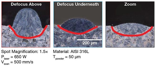
Figure 3. A quality comparison of enlarged spot sizes in melted track elevations of ring-mode beam shapes. With the zoom configuration, the beneficial effects of a ring mode can also be used for an enlarged laser focus. The elevation of the melted track is much lower for the zoom configuration, showing a homogeneous and wide connection area. Courtesy of Technical University (TU) Munich/RAYLASE.
Therefore, both changes will negatively affect the production time, counteracting the desired increase of the build rate. From the VED formula, it becomes clear that the best way to keep the volumetric energy input constant with increasing build rate is by increasing the laser power.
In recent years, more high-power fiber lasers have become available at an accessible price level in the market. These lasers offer output power of up to multiple kilowatts with excellent brilliance, allowing the beam to be focused in the field to the minimum spot diameter. Due to their fiber, beam delivery can be kept simple, and their standardized interfaces allow easy integration into AM machines.
The use of such high-power lasers has been widely adopted in macro welding. Still, its application in LPBF has remained limited, mainly due to limitations in the optical setups of the beam deflection units. Typical scan systems for AM use small mirror sizes optimized for high scanning dynamics. However, these mirrors limit the maximum laser power and require f-theta lenses to focus the laser in the field. These complex lenses also limit the use of high laser powers due to thermal lensing or back-reflections into the scan system.
Fortunately, recent developments in the field of beam deflection units helped to overcome these hurdles and made the use of high-power lasers also applicable to LPBF. Moving from an open scan head design to a sealed and highly integrated scan system with defined interfaces ensures a dust- and dirt-free environment inside the scan system. Combined with optimized mirror coatings, a preadjusted collimation and fiber coupling unit, and modern cleanroom production facilities, these scan systems are now suitable for laser powers of up to 2 kW.
Additionally, due to the use of digital electronics, the tuning of modern beam deflection units can be tailored specifically to the AM application, offering high dynamics for larger mirror sizes. This enables the use of alternative prefocussing optics and eliminates the need for an f-theta lens, another factor limiting the maximum acceptable laser power in LPBF applications.
These recent optimizations of beam
deflection units allow the use of high-power lasers in the LPBF process. Further, these laser sources can provide enough extra laser power to keep the VED constant while the build rate is optimized. Also, they offer the necessary flexibility when adapting process parameters.
The benefits of beam shaping
When using higher scan speeds to improve the build rate of an LPBF process, it is crucial to increase the laser power to keep the VED in the powder constant. However, the laser power cannot be increased unlimitedly, because at higher laser power, second-order effects start to occur in the melting process.
Most LPBF machines use single-mode laser sources with a well-defined Gaussian spot profile, so the intensity in the center is significantly higher compared to the outer regions. This high difference in laser power within the spot causes steep temperature gradients, which result in stress in the material. This can lead to material imperfections, lowering its mechanical properties or even resulting in defects such as cracks or unmelted areas. The high laser power in the center also might evaporate part of the powder, forming spatters or resulting in gas bubbles inside the melt pool, forming pores.

Figure 4. Variations in the beam profiles of an AFX laser magnified at 1.5×, achieved through zoom and defocus techniques. The images illustrate that the zoom configuration maintains the integrity of the original beam profile. In contrast, defocusing leads to a discernible degradation of the beam’s clarity. Consequently, the beneficial characteristics of ring or flat-top beam profiles are compromised under defocusing conditions. Courtesy of Technical University (TU) Munich/RAYLASE.
Although such effects can generally occur at high laser powers, it is the Gaussian spot profile of single-mode lasers that worsens the situation. Due to the high intensity in the center of a Gaussian spot, such effects set in much earlier at much lower laser power.
The advent of beam-shaping technologies represents a significant leap forward in the control and optimization of the manufacturing process. By altering the intensity profile of the laser beam, these technologies ensure a more consistent melt pool geometry, thereby mitigating the risk of overheating and reducing the occurrence of spatter — a by-product of rapid material vaporization. Furthermore, the even energy distribution prevents excessive powder removal from the melt track vicinity, countering powder denudation effects.
Implementing beam shaping into the LPBF machine requires optical elements with little spot variation over the work field and precise alignment of the lenses. To use the maximum advantages of the beam-shaping optics in the powder, the modified focus should be combined with high laser powers, which may introduce thermal lensing that can disturb the final spot profile in the powder.
The rise of highly integrated beam deflection units with pre-aligned optics represents an important development that simplifies the integration of beam-shaping technologies into LPBF machines. Their internal fiber coupling and collimation
optics are optimized to influence the laser beam as little as possible using suitable lenses and coating and reproducible alignment procedures. To maximize the
permitted laser power of the LPBF
system, f-theta lenses are abandoned and prefocus deflection units are used. The beam shaping imposes significant requirements on the alignment of the lens system, the uniformity of the movement, and the dynamics of the focus adjustment. Modern pre-aligned integrated beam deflection units can provide the required precision and dynamics and help to keep the optical deviation as low as possible.
Beam shaping technologies represent a cornerstone in the ongoing advancement of LPBF. If integrated properly, they
offer a powerful means to refine process parameters, boost productivity, and
significantly improve part quality.
Advantages of in-focus spot enlargement
Beyond increasing layer thickness or scan speed, increasing the hatch distance is an important parameter for optimizing the build rate of the LPBF process. Doubling the spacing significantly reduces the necessary scan vectors and, hence, the required exposure time of each layer. However, wider hatch spacing requires larger spot sizes to ensure a sufficient overlap between neighboring scan paths. Such increased spot sizes have a negative effect on the minimum feature size of an LPBF machine, because fine details require a small focus.
For this reason, modern LPBF machines use dynamic defocus solutions. By integrating additional optics or by using prefocus beam deflection units, they can defocus the laser into the powder, which results in a larger spot size in the powder. This technology enables spot size enlargement during the build process. It can combine a fine focus for small features or the part’s hull and allow the spot to increase for the efficient filling of internal bulk material.
While such defocus solutions might be a pragmatic start for optimizing the hatch distance, they show limitations when combining spot enlargement approaches with beam-shaping technology. As the modified spot profiles of a ring or a top hat are only well defined in the focus, they start to blur as soon as a shift out of the correct focus plane occurs. Therefore, to benefit from the shape of a doughnut or a top hat for small features as well as for large-area filling, a different optical setup becomes necessary: the zoom axis. This setup uses an additional lens system to keep the focus on the z-level of the powder while enlarging the spot size. However, it requires a precise and synchronous movement of the lenses inside the zoom axis. Additionally, a sealed scan solution and a clean production environment for the beam deflection units become mandatory because, due to the zooming, the power density on the optics can significantly increase.
Fortunately, the advent of modern, highly integrated beam deflection units enabled the use of such zoom optics for in-focus spot enlargement. And, this proliferation offers a promising avenue for advancing LPBF processes. By enabling larger spot sizes without losing focus, it enhances the efficiency of the manufacturing process and brings up new possibilities for producing intricate designs at high throughput rates.
As technology continues to evolve, its application across various industries is expected to grow, further demonstrating its value in improving both productivity and part quality in AM.
Potential for further optimization
Modern beam deflection units and associated technologies — high-power laser systems, beam shaping, and in-focus spot enlargement — have had and are still having a transformative effect on the build rate of LPBF processes. Through the strategic manipulation of process parameters and the adoption of innovative hardware, the LPBF technique has seen significant advancements in efficiency, quality, and the ability to create complex geometries.
However, the potential for further optimization remains vast, particularly through refined calibration processes and the integration of sensors for in-line process control and quality assurance. An optimized calibration process can significantly reduce setup times and enhance repeatability, ensuring that each build starts from the most accurate baseline possible. Similarly, the smooth integration of sensors for real-time monitoring opens new avenues for adaptive control strategies, where process parameters can be dynamically adjusted based on direct feedback from the build environment. This not only promises to increase the build rate by minimizing defects and rework but also enhances the overall reliability.
Exploring the frontier of LPBF technology illuminates that recent advancements have unlocked remarkable improvements in build rate efficiency. Innovations in high-power laser systems, beam shaping, and in-focus spot enlargement are revolutionizing manufacturing precision, paving the way for new possibilities in AM and setting new standards for part quality and the productivity forecast of the LPBF process. As refinements of these aspects continue, along with the advancements discussed, the future of LPBF looks
toward not only faster production times but also greater part quality and process reliability, marking a significant step forward in the AM landscape.
Meet the authors
Wolfgang Lehmann is head of product management at RAYLASE with more than 20 years of experience in the laser field. He is responsible for the AM MODULE and SCAN-FIELD-CALIBRATOR, two AM-specific products in the RALAYSE portfolio; email: [email protected].
Jan Bernd Habedank is head of the Technical Competence Center at RAYLASE. A laser technology expert, he served as head of the
Department for Joining and Cutting Technology at TU Munich before joining RAYLASE; email: [email protected].
Harnesh Singh is director of sales and
marketing at RAYLASE and has supported customers with their projects in laser technology since 2005. By managing and growing big key accounts in the additive manufacturing (AM) sector, he has gained deep insights into the AM processes; email: [email protected].